- Anti-scan Pattern
- Anti-Stokes Ink
- Background Image
- Bar-code
- Binding Technique
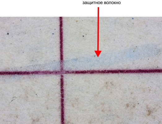
- Bleeding Ink
- Blind Embossing
- Book Block
- Card
- Clear Window
- Cover
- Covert Laser Readable Image (CLR)
- Data Page
- Demetallization
- Diffractive Identification Element DID Patch
- Digital Printing
- Document Construction
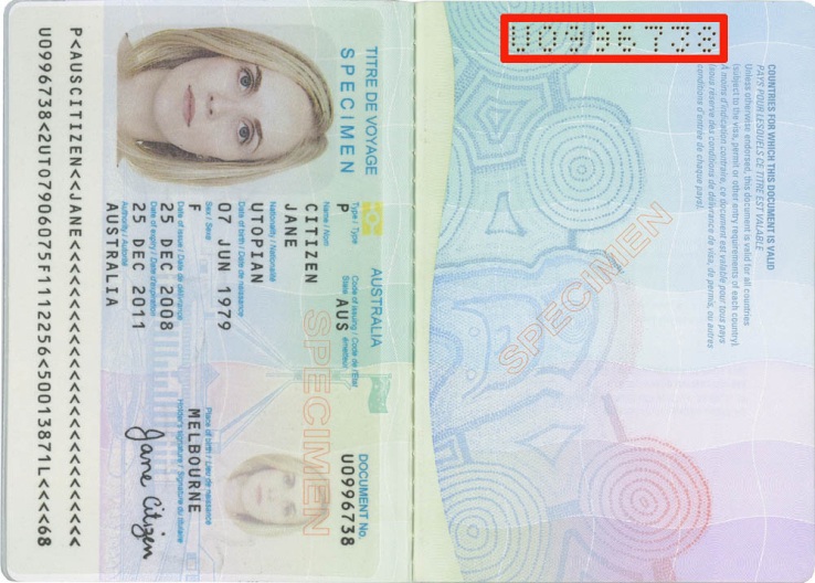
- Document Number
- Document Personalization
- Electronic Document (E-Passport)
- Endpaper (Inside Cover)
- Eyelets / Rivets
- Fingerprint
- Floating image
- Foil Stamping
- Folded Document
- Glossy Laminate Overprint
- Gravure Printing
- Guilloches
- Holder’s Photo
- Hologram / Kinegram
- Holographic Microparticles OVDot
- Illumination
- Insert
- Intaglio
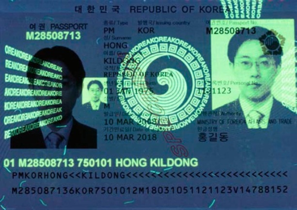
- IPI – Invisible Personal Information
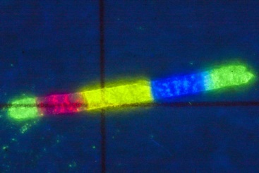
- IR-fluorescent Inks
- IR-metameric Inks
- Iridescent Ink
- Iridescent Laminate
- Laminate
- Laminate Overprint
- Laser Engraving
- Latent Filter Image LFI
- Latent Image KIPP
- Latent Image MASK
- Latent Image PEAK
- Latent Multicolour Image
- Latent Scrambled Image
- Lenticular Technology
- Letterpress
- Magnetic Ink
- Magnetic Stripe
- Metallic Ink
- Metameric Inks Pair
- Microprinting
- Moire Variable Colour (MVC)
- Multiple Laser Image MLI / CLI
- Offset Printing
- One-sheet Paper (Single Sheet Document)
- Optically variable identification element FEEL-ID
- Optically Variable Identification Element FUSE-ID
- Optically Variable Ink (OVI)
- Optically Variable Ink with Embossing
- Optically Variable Magnetic Ink (SPARK, OVMI)
- Optically Variable Printed Image Dynaprint
- Orlov Printing
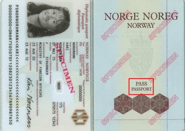
- Passport
- Passport Book
- Perforation
- Photochromic Ink
- Photographic Process
- Planchettes
- Rainbow Printing
- Retroreflective Coating
- Rip Cuts
- Screen Printing
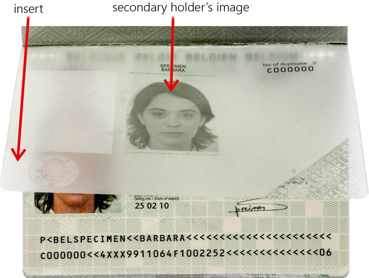
- Secondary Holder’s Image
- Secure Core Print (SCP)
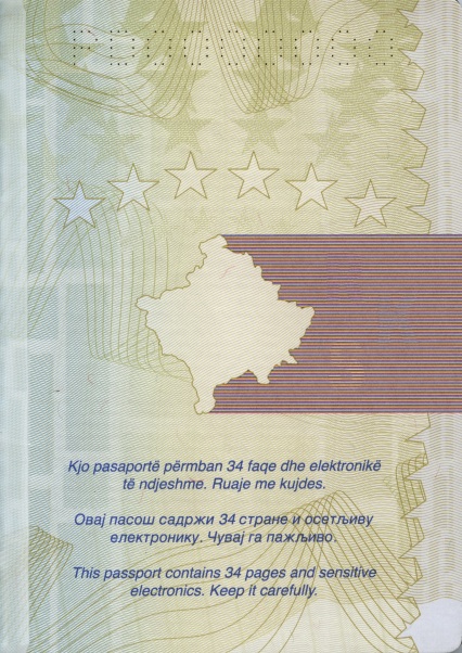
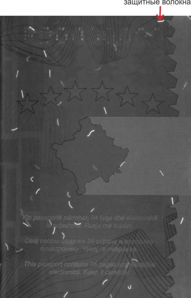
- Security Fibres
- Security Thread
- See-through Register
- Self-verifying Filter
- Slit Raster Technology
- Spine
- Stamp (Seal)
- Stitching Thread
- Substrate
- Thermochromic ink
- Thermographic Printing
- Thin-film Interference
- Travel Document
- UV-fluorescent Hi-lites
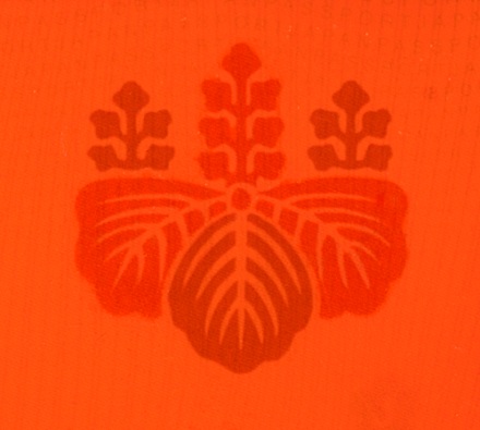
- UV-fluorescent Ink
- Varnish Coating
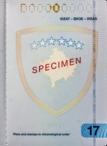
- Visa
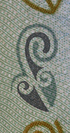
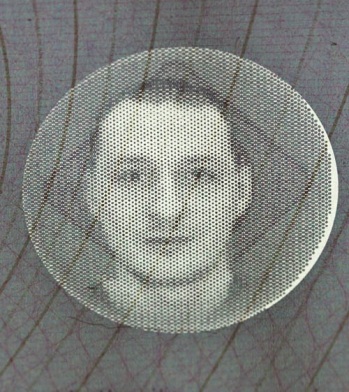
- Watermark
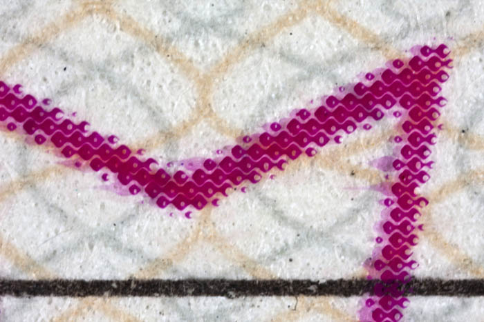
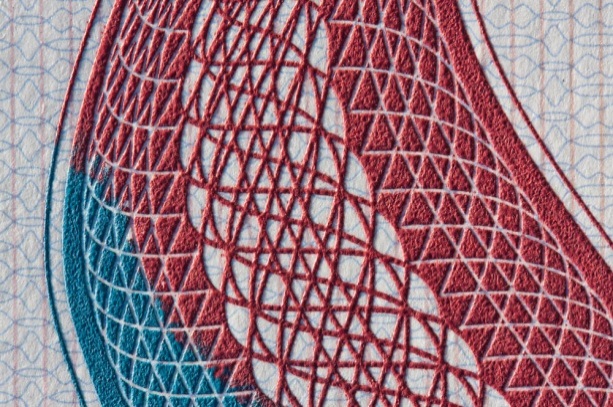
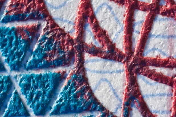
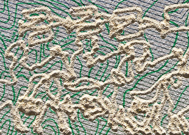
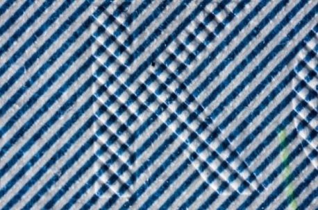
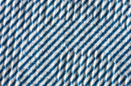
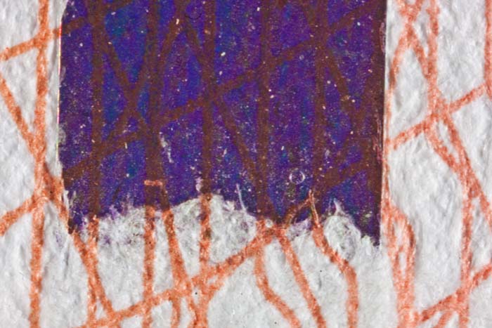
Images or patterns formed by regular parallel multidirectional (fig. 1) strokes or raster elements (fig. 2). When copying or reproducing such images, moire appears on prints as a colorful tangle of lines, bright and dark stripes and spots, etc. Moire appears as a result of two regular patterns overlay: strokes or raster of the original printed image and CCD (charge-coupled device) image sensors of digital printers or copiers.

a |

b |

c |
|
Fig. 1. Latvia. Passport: |
||

a |

b |
|
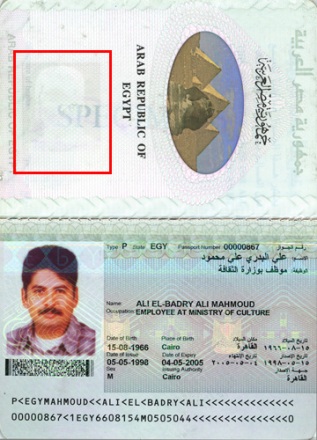
Fig. 2. Egypt. Special passport: |
|
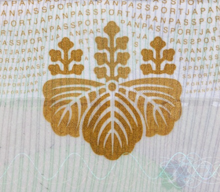
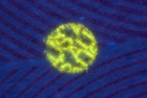
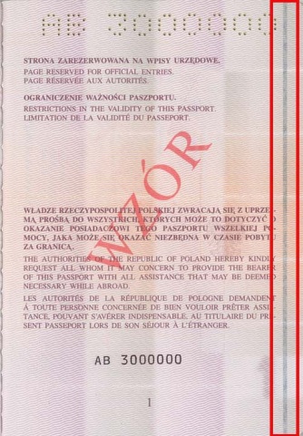
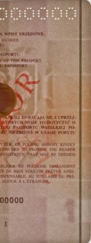
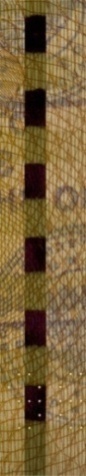
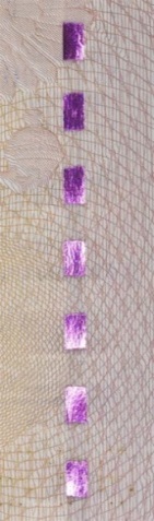
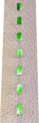
An ink which contains crystals of rare-earth metals (ytterbium, thulium, etc.) and glows when exposed to IR light of high intensity. Luminophores which glow green (fig. 1) are the most commonly used.
|
а |
b |
| Fig. 1. Poland. Official passport: а — spread (page 20–21); b — the same image, anti-Stokes green luminescence exposed to IR light |
|
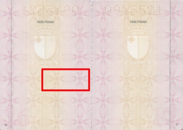
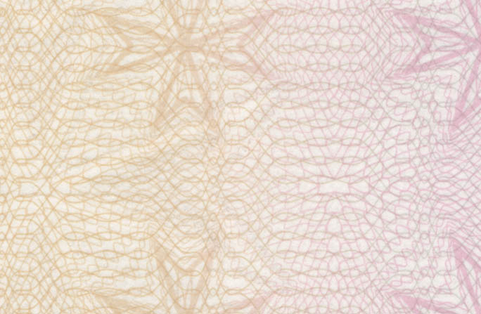
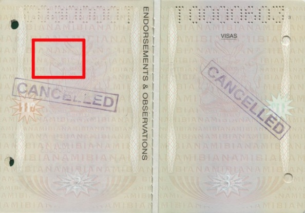
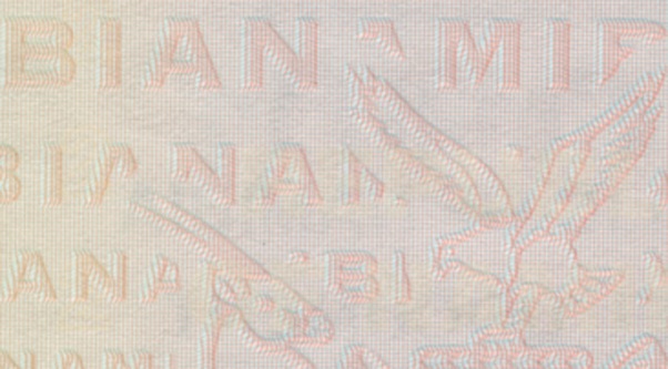
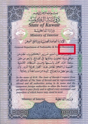
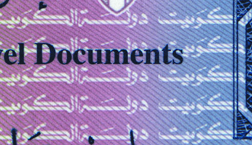
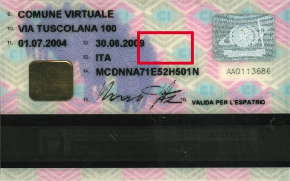
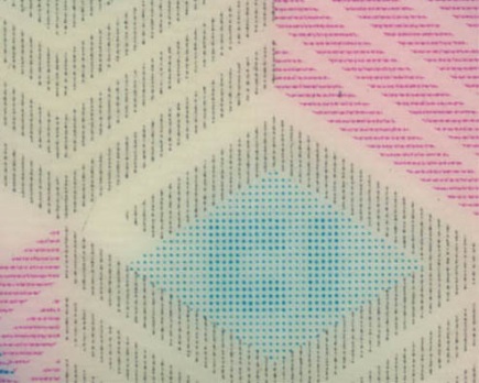
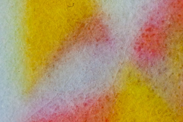
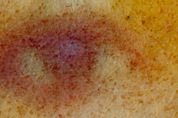
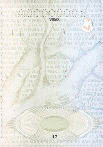
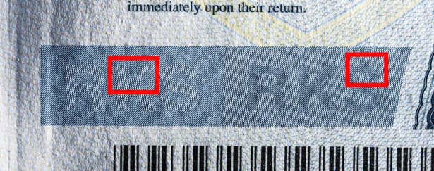
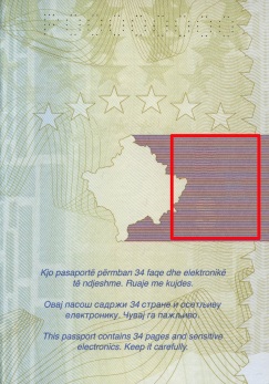
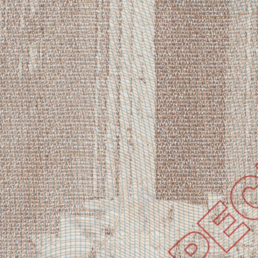
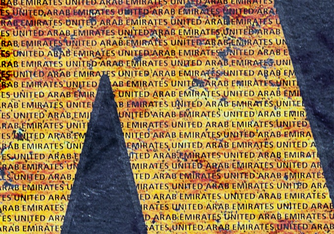
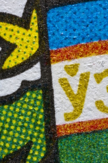
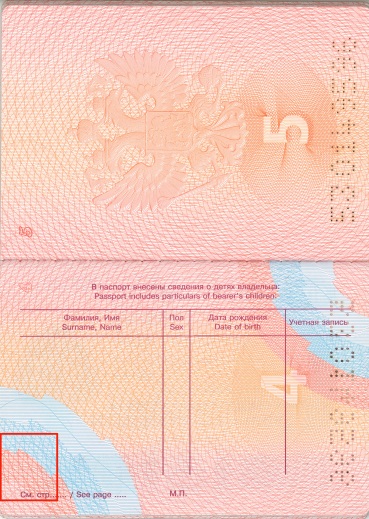
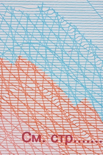
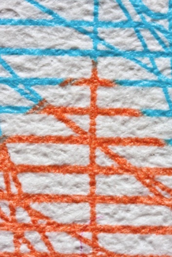
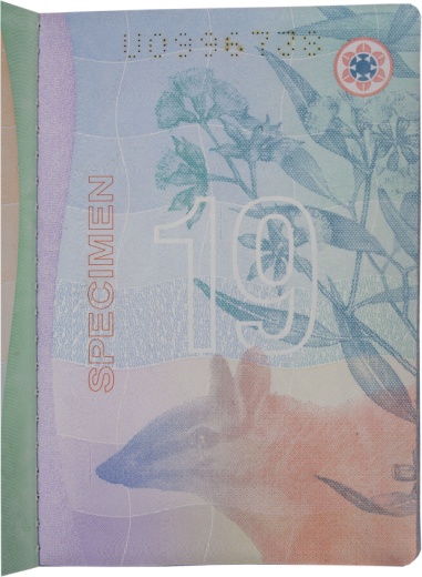
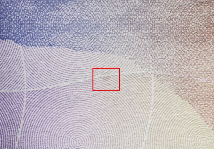
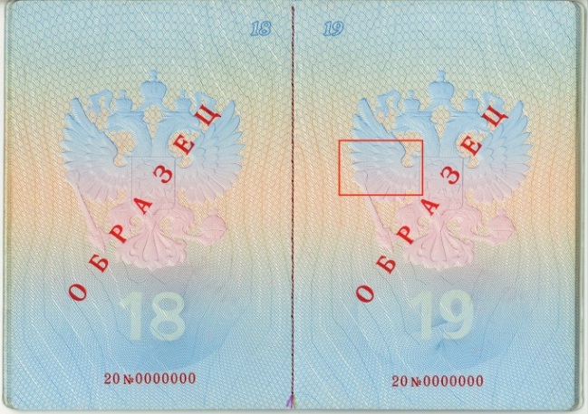
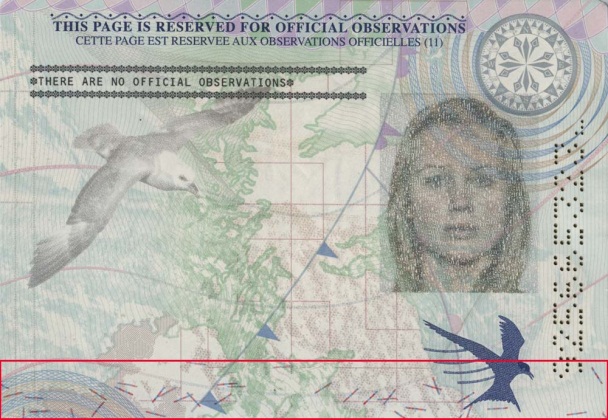
An image or an ornamental pattern printed on the background. It is used as a background for other images, serial numbers, text or notes. The image prevents both full and partial forgery because it is damaged during mechanical or chemical erasure.
Background image contains:
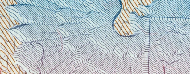
- regular pattern (fig. 1), intertwined lines which can have different thickness and form pseudo-volume elements due to sharp breaks (fig. 2);
- microprinting;
- design elements in the form of a colorful flood filling (fig. 3);
- other raster elements (dots, strokes) or special anti-copy patterns (fig. 4).
Background images are printed by offset, rainbow or Orlov printing using special security inks.
a |
b |
|
Fig. 1. Malta. Passport: |
|
a |
b |
|
Fig. 2. Namibia. Travel document: |
|
a |
b |
|
Fig. 3. Kuwait. Passport: |
|
a |
 b b |
|
Fig. 4. Italy. Identity card: |
|
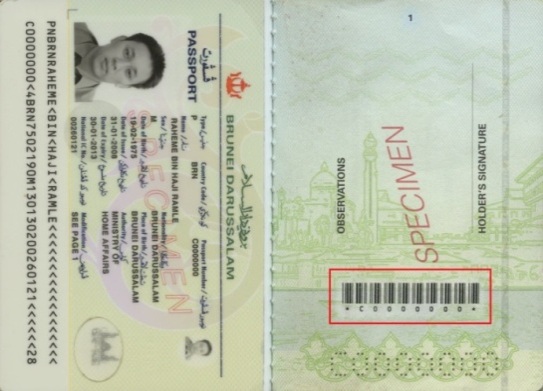
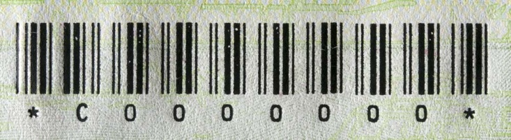
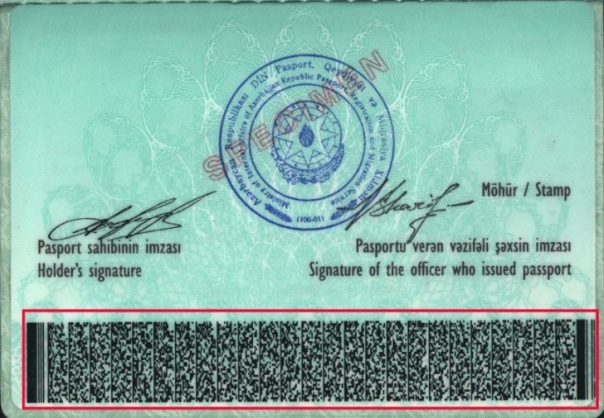
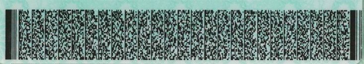
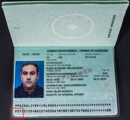
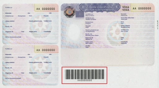
Graphic information in the form of a sequence of figures, lines of different thickness and white stripes or just lines and other geometric figures. This information is read by special devices.
A bar-code is printed using inks which may contain special security features (UV-luminescence, ferromagnetic components, etc.).
Types of bar-codes:
- linear bar-code (1D) bar-code is encoded and read in one direction (fig. 1);
- two-dimensional (2D) bar-code is encoded and read not only horizontally but vertically (fig. 2).
a |
b |
|
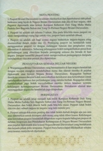
Fig. 1. Brunei. Passport: |
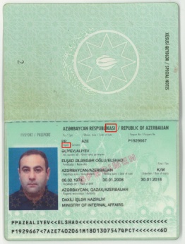
a |
b |
|
Fig. 2. Azerbaijan. Passport: |
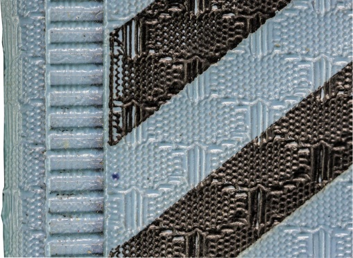
A method of stitching sheets of a folded book block.
The main techniques used for passport book sewing:
- side stitching (fig. 1);
- saddle stitch method (fig. 2–4).
In the first case sheets of a book block bound by a saddle stitching and sewed by a thread along the binding edge, i.e. at a certain distance from the spine. In the second case sheets are bound by a saddle stitching and joint by a thread or metal staples along the whole binding edge (fig. 4).

Fig. 1. Great Britain. Passport. Side stitching of a block bound by a saddle stitching |
a |

b |
|
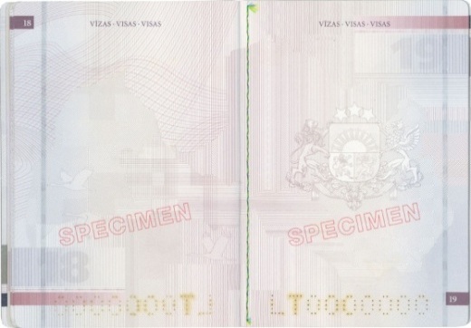
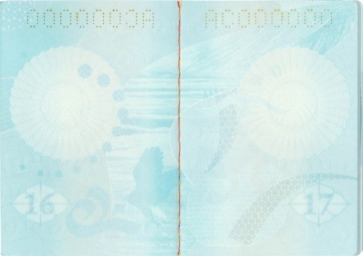
Fig. 2. Latvia. Travel document: |
|
a |
b |
|
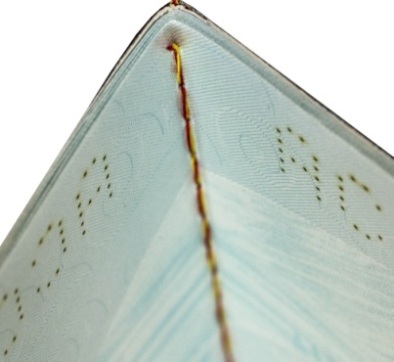
Fig. 3. Kyrgyzstan. Passport: |
|

a |
b |
|
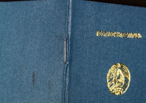
Fig. 4. Belarus. Refugee travel document: |
|
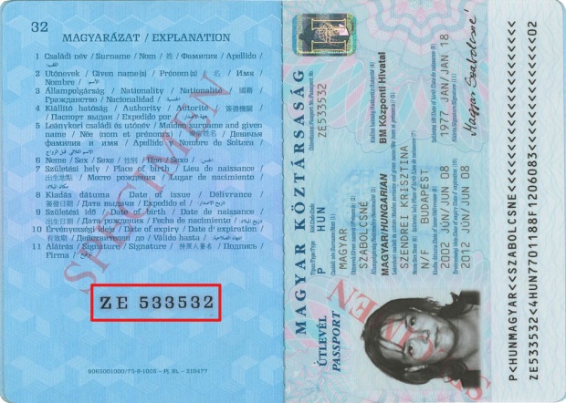
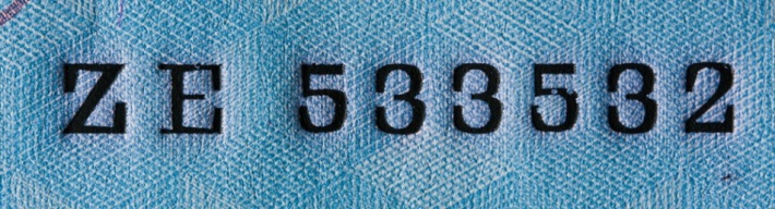
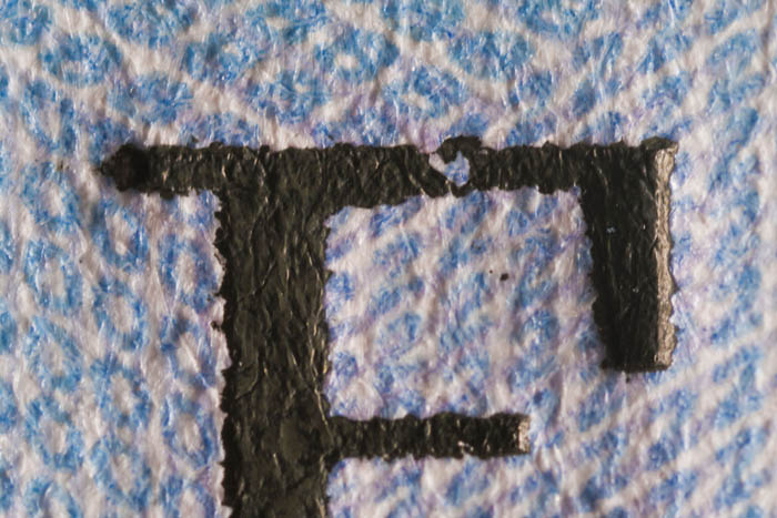
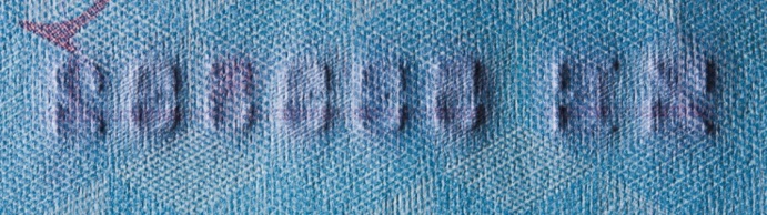
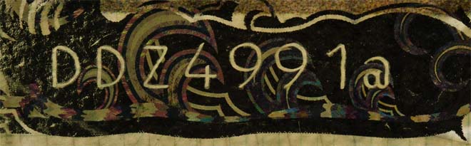
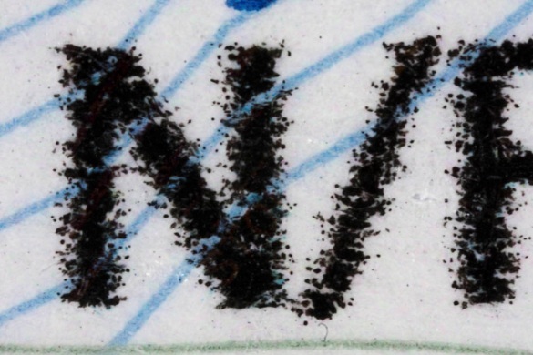
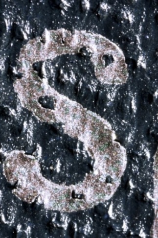
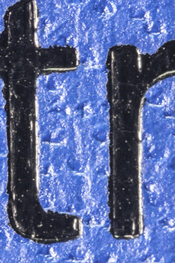
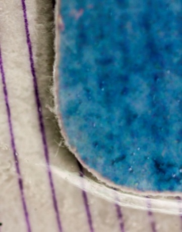
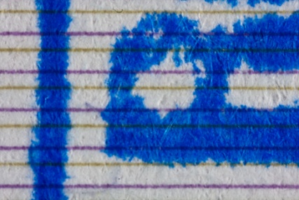
A black security ink containing component which penetrates a printing substrate – pores. It colors the paper red or blue in the form of a colorful halo from both front and reverse sides (fig. 1). A bleeding ink is used for applying numbers in passports and travel documents by the letterpress technique.
a |
b
c |
d |
|
|
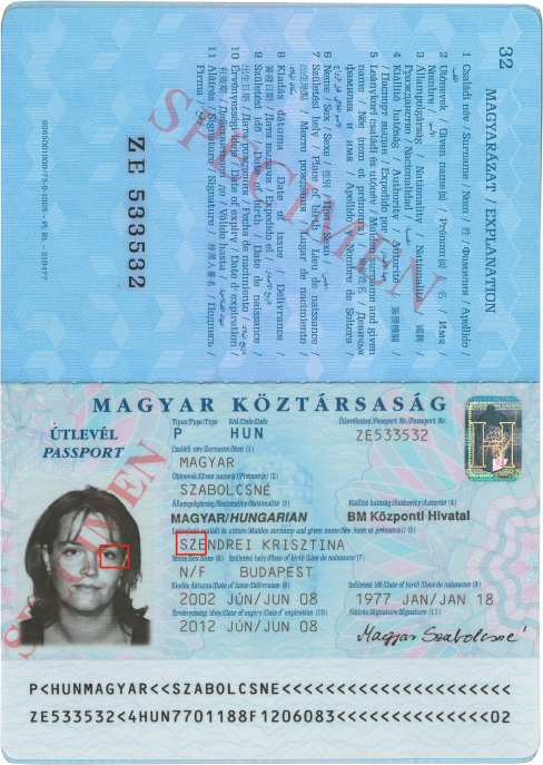
Fig. 1. Hungary. Passport: |
|
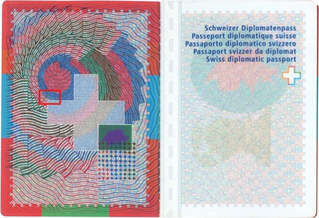
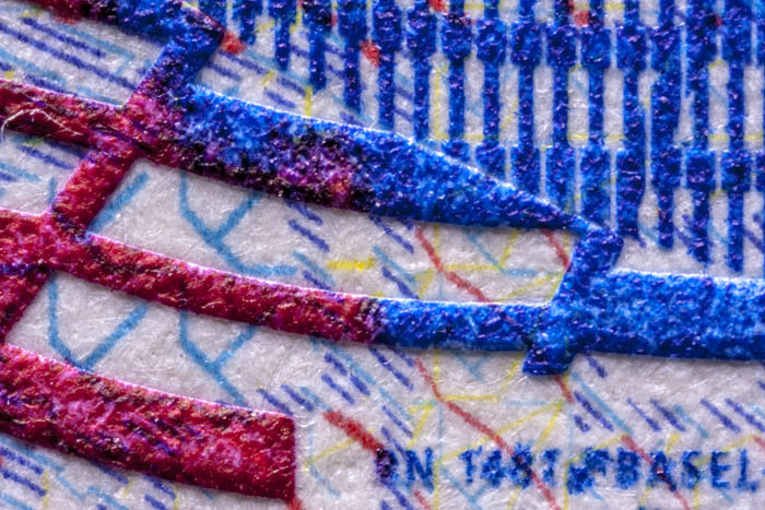
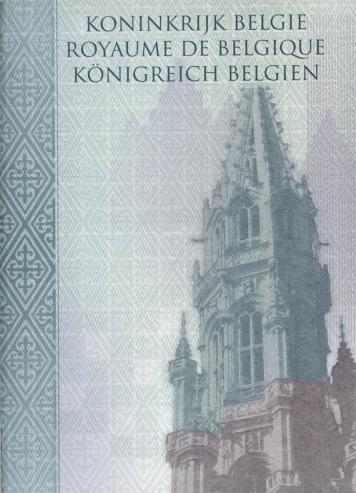
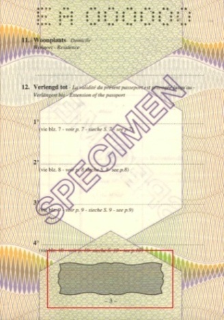
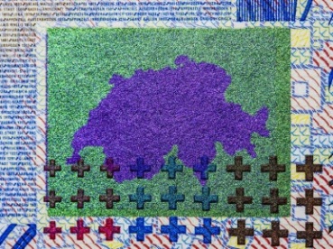
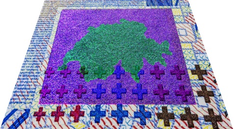
A colorless relief image applied to the substrate by deforming the material under pressure and heat. The image is palpable and used both for paper and polymer materials (embossing) (fig.1). It is visible under oblique light. A colorful image gradually transforming into blind embossing is a more complex security feature (fig. 2). Blind embossing is used on Images, texts and microprinting (fig. 3).
|
a |
b |
c |
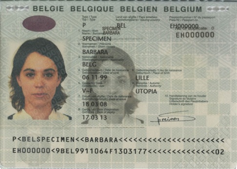
| Fig. 1. Belgium. Passport: а — data page, polymer transparent insert – verification filter and page. 3; b — text. Embossing on a polymer substrate; c — the same image, zoomed fragment under oblique light. |
||
|
a |
b |
| Fig. 2. Russia. Passport: а — page 3, general view at a right angle; b — blind embossing gradually transforming into a colorful image. Intaglio under oblique light |
|

a |

b |
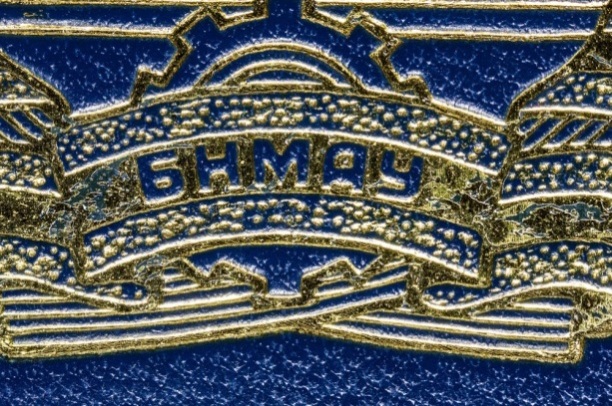
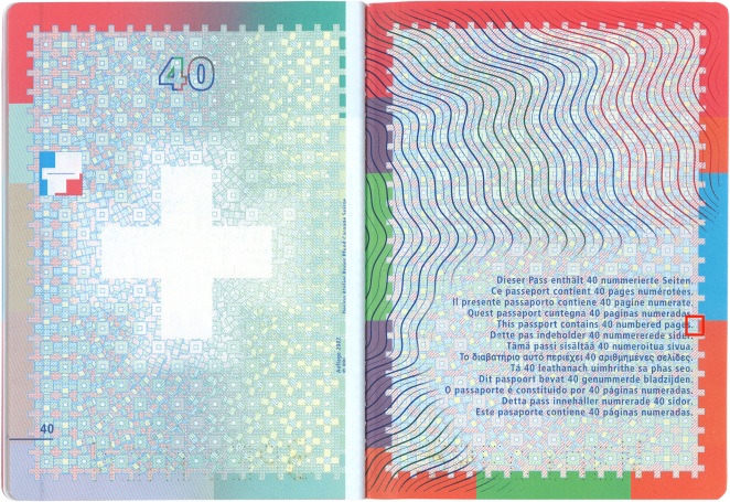
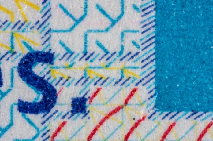
| Fig. 3. Switzerland. Passport: а — data page; b — microprinting. Embossing on a polymer substrate. |
|
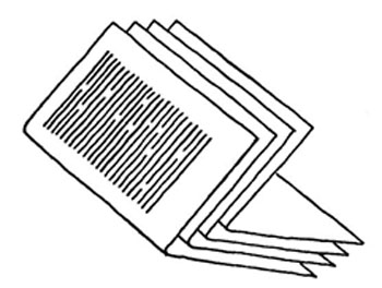
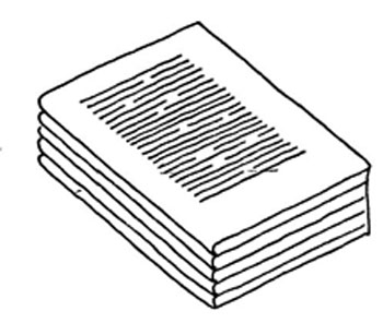
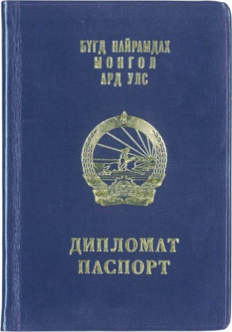
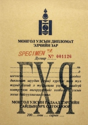
A type of a document construction in the form of a folded set of sheets or sections which are formed as a single/multiple booklet. In a single booklet folded sheets are gathered together one inside the other (sheet into sheet) starting from the inside one (fig. 1a, 2). In the second case successively folded sheets are placed one upon the other (sheet to sheet) (fig. 1b).
a |
b |
 |
|
Fig. 1. Book block gathering methods: |
Fig. 2. Mongolia. Diplomatic passport. |
|
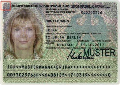
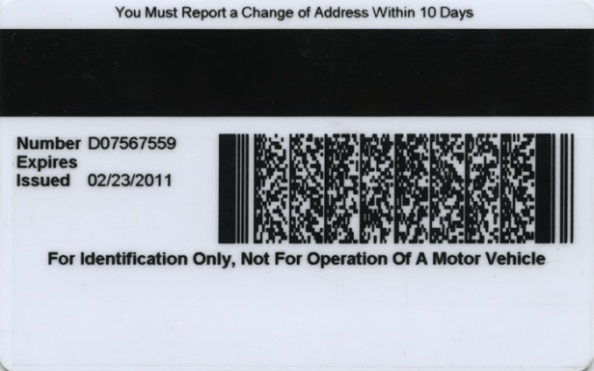
A type of a document construction in the form of a standard right-angled sheet. According to the ISO 7810 there are 4 types of a card size:
| Type | Size | The main use |
| ID-1 | 85,60 mm×53,98 mm | ID-cards, driver licenses, bank cards |
| ID-2 | 105 mm×74 mm | ID-cards, driver licenses, vehicle documents, visas |
| ID-3 | 125 mm×88 mm | Passports (plastic inserts and visas) |
| ID-000 | 25 mm×15 mm | SIM cards, may be a part of a ID-1 card |
Thickness of all cards — 0.76 mm.
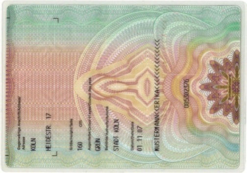
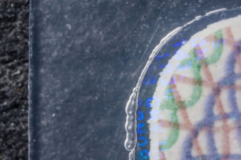
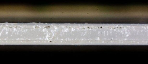
A card can be made of a laminated homogeneous (fig. 1) material or a multilayer composite material (PVC, polycarbonate) (fig. 2) with or without inserts.
There are following types of card according to the technology:
- cards without any digital data (fig. 1);
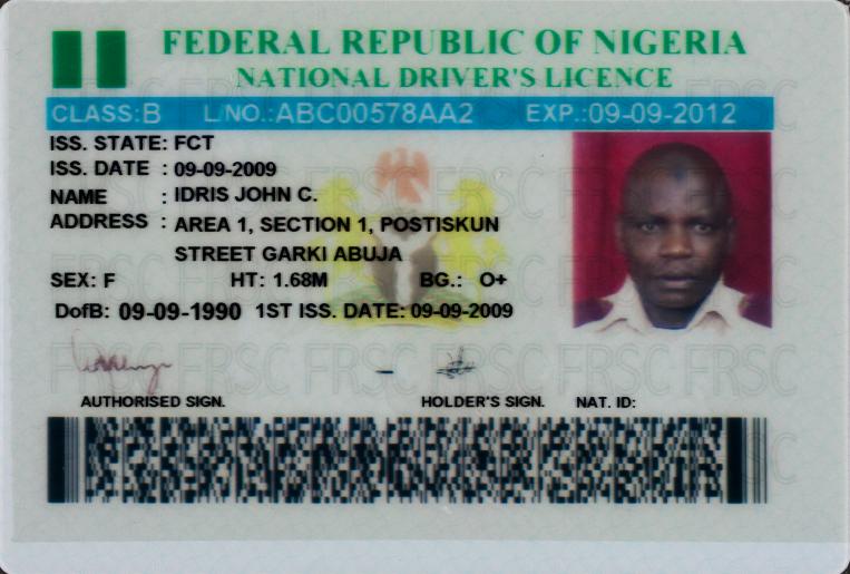
- cards with a bar-code (fig. 2);
- cards with a magnetic stripe (fig. 3);
- chip cards (fig. 4);
- combined magnetic chip cards.
a |
b |
c |
d |
|
Fig 1. Germany. Identity card (size 115×75 mm): |
|
a |
b |
|
Fig. 2. Nigeria. Driver license (size 98×67 мм): |
|
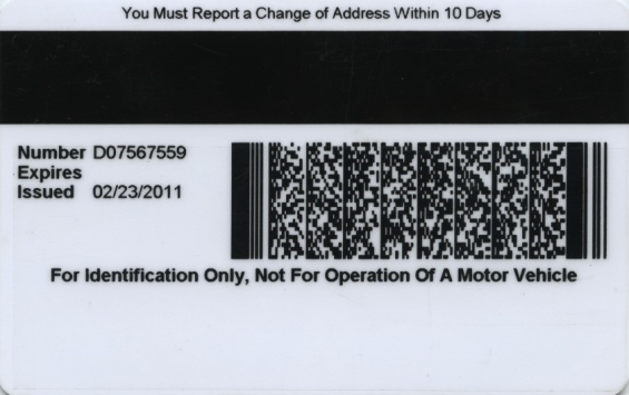
Fig. 3. The United States of America. Identity card. |
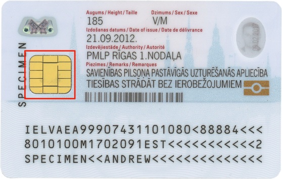
Fig. 4. Latvia. Identity card. |
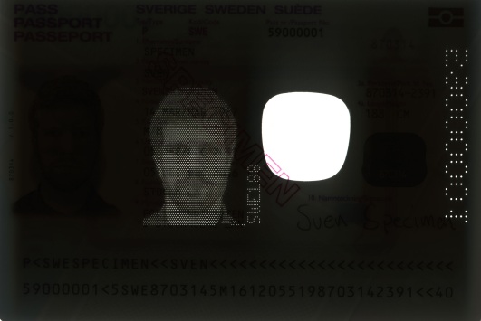
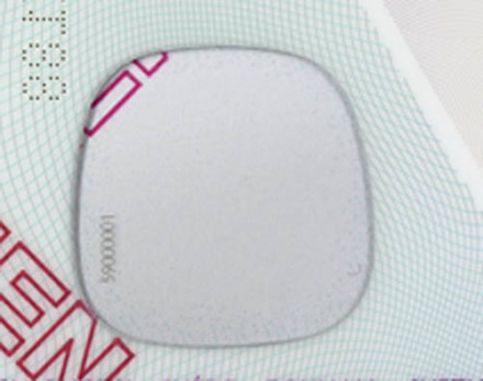
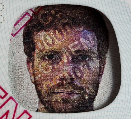
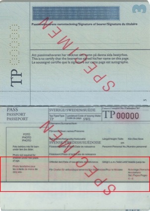
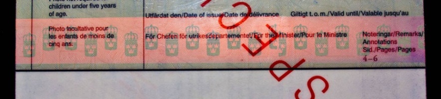
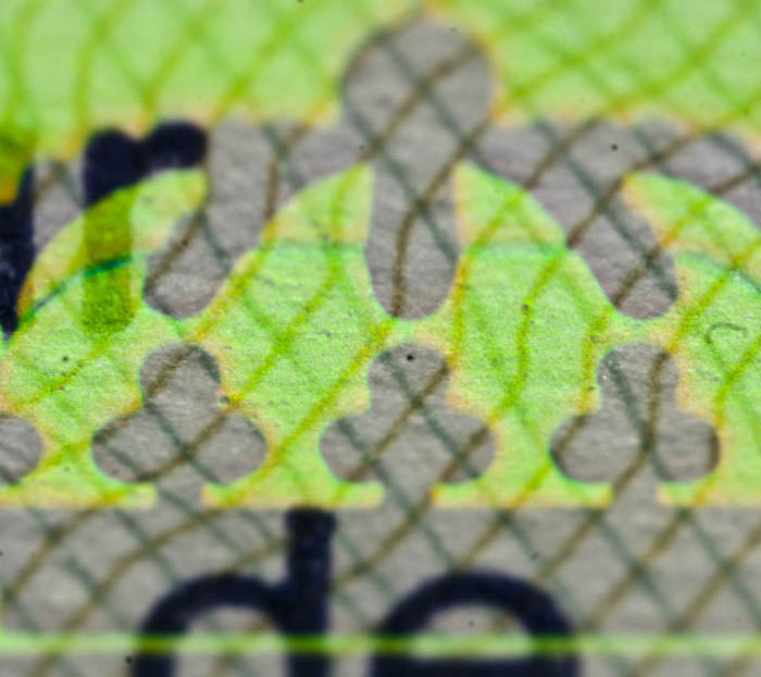
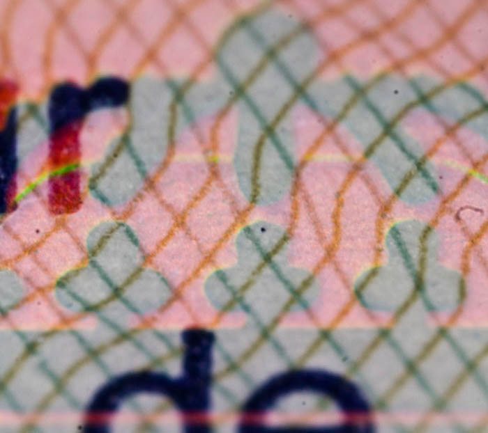
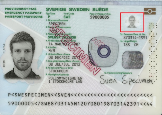
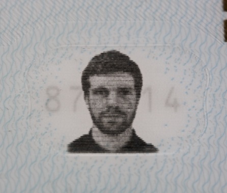
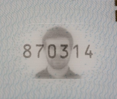
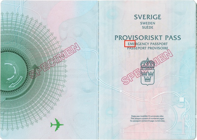
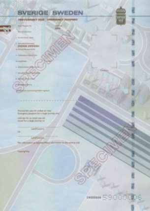
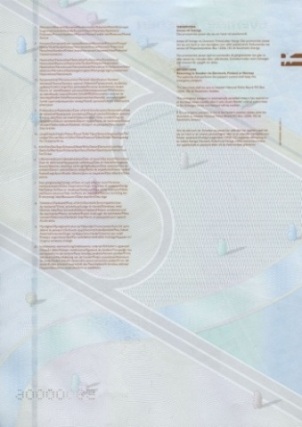
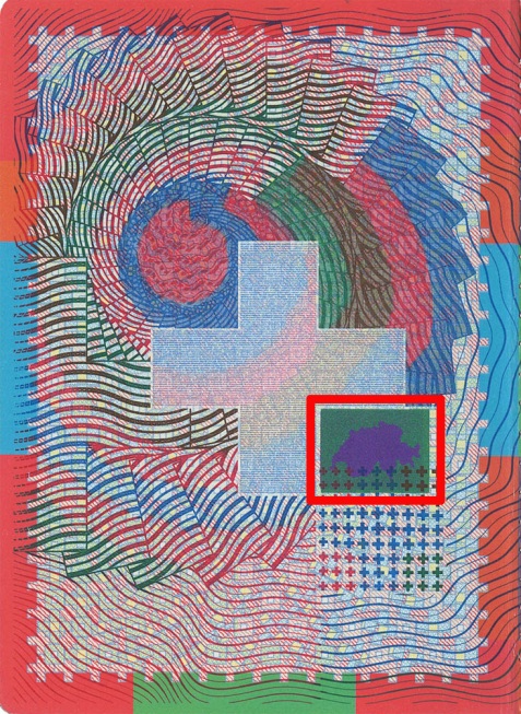
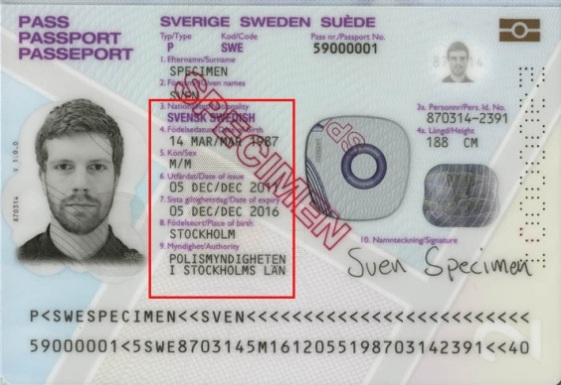
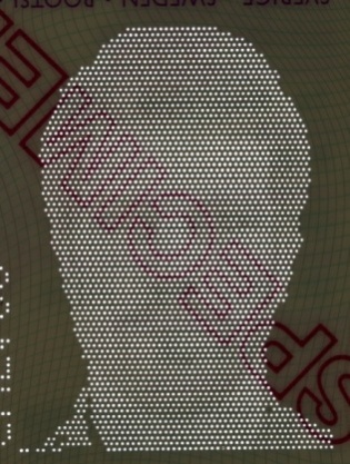
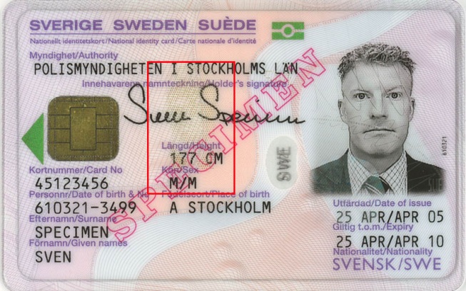
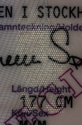
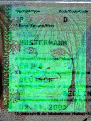
A non-printed area of a substrate which is transparent, when viewed against the light (fig. 1). Clear window is used for applying additional holder’s image used as a verification filter or for visualization of latent scrambled information.
a |
b |
c |
d |
|
Fig. 1. Sweden. Passport: |
|
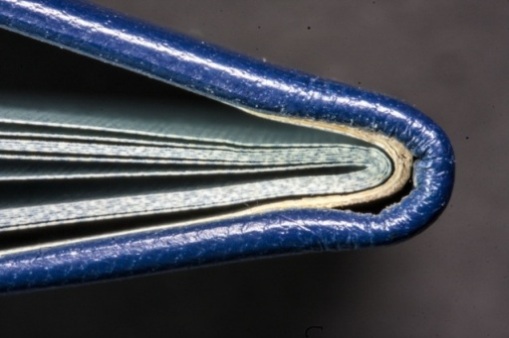
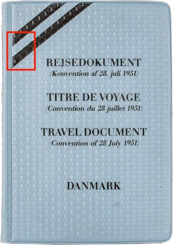
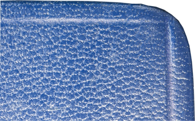
An outer document coating, a decoration element in the form of a sheet of a heavy paper or a board covered with a synthetic material.
Covers classification
By material:
- single-layer covers are made from one sheet of the material (fig. 1);
- multi-layer (fig. 3) cover is a board covered with a synthetic material, a leather (fig. 2), a fabric or a paper.
By design: with design elements applied with inks by any printing method, foil stamping, blind embossing.
By hardness:
- soft;
- hard.
By form of angles:
- with right angles;
- with rounded angles.
By binding method:
- stapled (without endpapers);
- glued to endpaper.
Usually sizes of a book block and a cover are the same. If a cover is larger than a book block it overlaps a block from three sides in the form of edges.
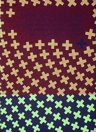
Printing with UV-fluorescent (fig. 3c) is an additional security feature of a cover.
a |

b |
c |
d |
|
Fig. 1. Denmark. Travel document: |
|
a |

b |
c |
d |
|
Fig. 2. Mongolia. Diplomatic passport: |
|
a |
b |
c |
d |
|
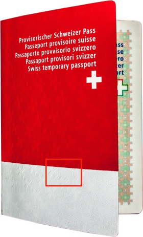
Fig. 3. Switzerland. Temporary passport: |
|
COVERT LASER READABLE IMAGE (CLR)
A security mark — an image, a symbol or a text which is invisible by the naked eye and by means of a microscope. The image is visualized in laser beams with the help of special devices. A covert laser readable image is formed when recording hologram image using the method of the electron-beam lithography. A CLR image is an area on a hologram surface which has specific microrelief of 1 micron in size and a fraction of a micron in depth. A laser beam which is perpendicular to the surface of this area reflects from microrelief elements and forms an image on the device screen.
There are several types of a covert laser readable image:
- simple covert laser readable images consists of one image;
- dynamic covert laser readable images consists of several images which represents different phases of a moving object (a kind of an animated film);
- multilevel covert laser readable images consists of several images applied on the same area.
a |
b |
c |
d |
e |
f |
|
Fig. 1. Russia. Passport. Covert laser readable image: |
||
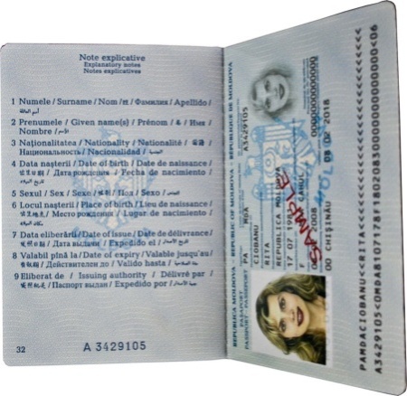
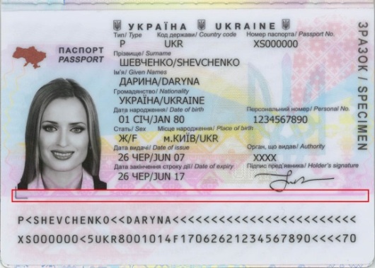
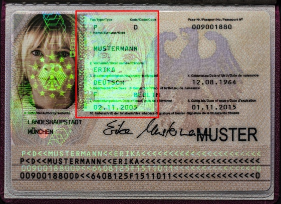
A page of a passport or a travel document on which the issuing state applies holder’s personal data and the issue and expiry dates. The main holder’s portrait is located on data page.
A data page of a machine-readable document contains a visual inspection zone and a machine-readable zone. A data page is filled according to certain standards to make a reading process in different countries easier. A data page may be located on an inner page (fig. 1), an insert or an endpaper.
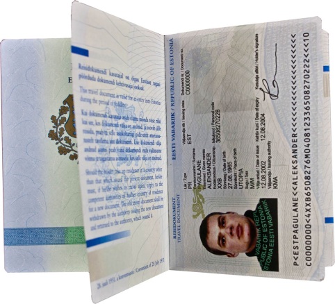
a |

b |
c |
|
Fig. 1. Data page location: |
||
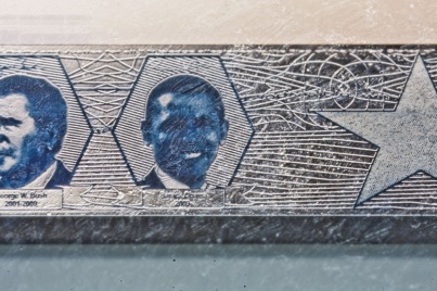
The process when a text or other design elements are removed from a metallic layer by a laser or chemical erasure and become visible when viewing against the light.
a |
b |
c |
d |
|
Рис. 1. Great Britain. Passport: |
|
DIFFRACTIVE IDENTIFICATION ELEMENT DID PATCH
DID — Diffractive Identification Device
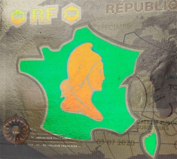
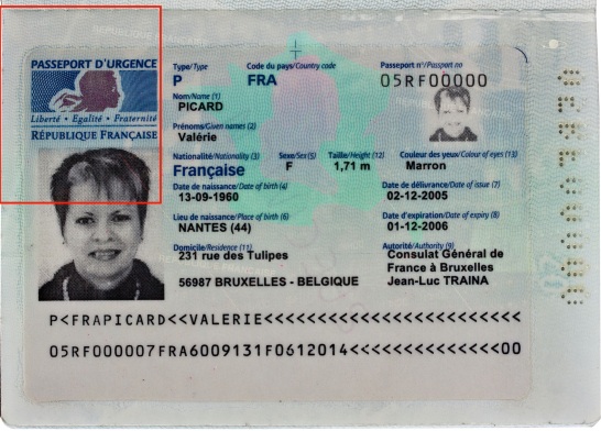
An optically variable image which contains elements changing the color at different angles of illumination and observation. A color changing effect determined by interference and linear polarization of light on diffraction gratings embedded in a transparent thin-film dielectric medium (fig.3). When the axis of observation is perpendicular to lines of a diffraction grating we may observe, for example, a green light. If the axis of observation is parallel to the grating lines an orange-red light is observed (fig. 1).
A color change is observed at different areas while rotating the image by 90° without changing the angle of observation (fig. 2).
In diffuse oblique light at a right angle a DID element is transparent (fig. 1a). Personal data remain visible.

a |
b |

c |
|
Fig. 1. France. Passport: |
||
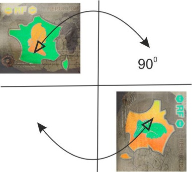
Fig. 2. Image rotation scheme for the visualization of a DID Patch element |
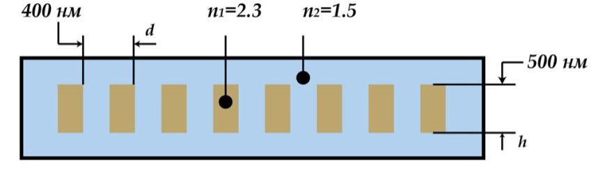
Fig. 3. Cross section of a diffraction grating: |
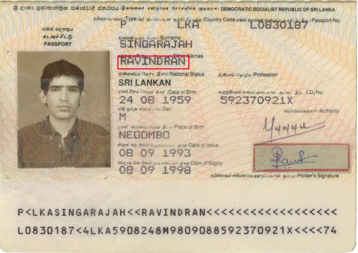
A printer is a printing device for applying digital information on a hard substrate without a printing plate. In identity documents a variable data about holder is applied by a printer on the data page and at the machine-readable zone. There are different types of printers depending on a printing technology: dot matrix, laser, inject, dye-sublimation.
Dot matrix (pin) printing
An image is formed by a print head, which consists of a set of pins driven forward by the power of an electromagnet. A print head moves line by line along the sheet. Pins hit the paper through the printing ribbon and a dot image is formed. The number of pins may vary from 9 to 24.
Characteristics of the print:
- clearly visible dot structure of text symbols (fig. 1);
- slight concave of every dot into the paper which is not observed on the reverse side.
a |
b
c |
|
Fig. 1. Sri Lanka. Passport: |
|
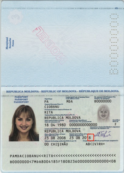
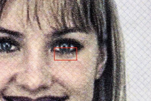
Laser printing (xerography)
An image is formed the following way: a laser beam illuminates dots on the drum corresponding to the symbols. These dots are charged and pick up powdered ink (toner). The toner is transferred to a paper and fused to it using heat of up to 200 °C.
Characteristics of the print:
- strokes are relief at dark areas of an image and glossy under oblique light;
- letter and figure strokes have a fringe along the edges. It is formed by burned toner particles (fig. 2d);
- zoomed colorful halftone images have the form of a regular raster dot pattern created by purple, blue, yellow and black elements (fig. 2b, c).
a |
b |
c |

d |
|
Fig. 2. Moldova. Passport: |
|
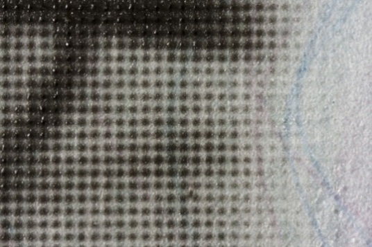
Inject printing
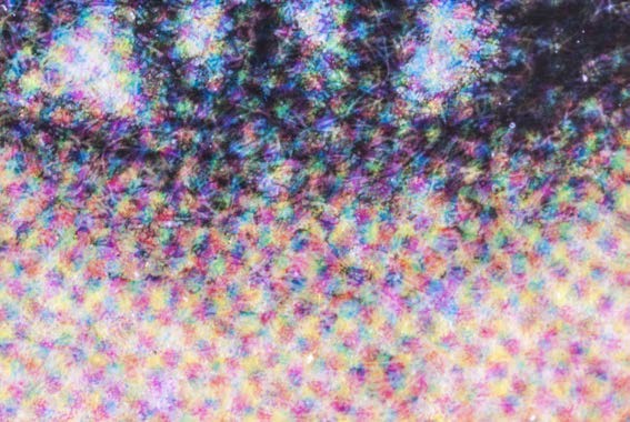
A non-contact printing method. Blue, purple, yellow and black liquid inks form a dot image by propelling them directly onto the paper surface with a high speed.
Characteristics of the print:
- images of letters, symbols and strokes are created by random blot shaped ink dots of purple, blue, yellow and other colors and 10–30 mcm size (fig. 3);
- smooth stroke edges (when zoomed).
a |
|
b |
c |
|
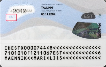
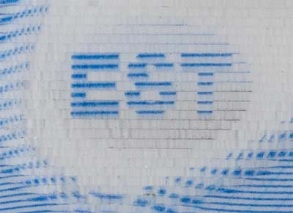
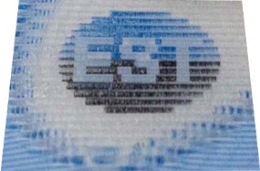
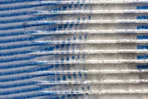
Fig. 3. Estonia. Passport. Inject printing: |
|
Dye-sublimation printing
An image is formed by means of a ribbon which is located between the printing head and the surface. Layers of sublimation dyes (yellow, purple, blue and black) are stored on a polyester ribbon. After the printing head changes its temperature the dye is heated and exhales transiting from the solid into the gas state without going through a liquid stage (it is called sublimation). When exposed to high temperatures, pores on the printing surface are opened and let the dye diffuse into deeper layers of the substrate. In the process of dye-sublimation printing a raster element is formed by the dye exhalation and the color mix before it is transferred to the printing surface. As a result smooth edges of raster elements are observed.
Characteristics of the print:
- full-color images have a smooth tone gradation (fig. 5c, 6c);
- oblique strokes of books and figures have graded edges (fig. 5d, 6e, 7c).
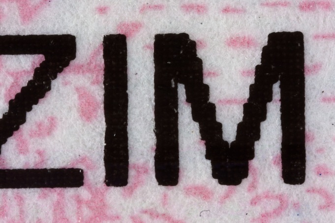
Thermal transfer printing is a type of a dye-sublimation printing. In this printing method, in comparison with previous one, an image is transferred to the printing surface directly from the ribbon of a certain color. Full-color halftone images have regular raster structure in the form of multicolor dotes (fig. 7).
a |
b |
|
Fig. 4. Dye-sublimation (а) and thermal transfer printing (b) scheme: |
|
a |
b |
c |
d |
|
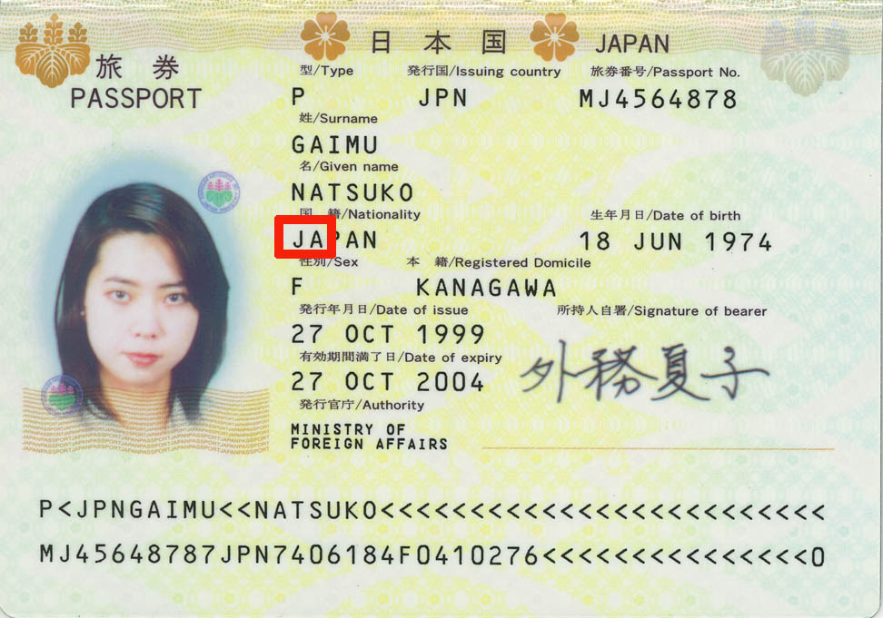
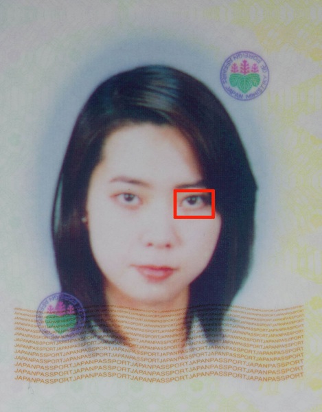
Fig. 5. Japan. Passport. Dye-sublimation printing: |
|
a |
b |
c |
d |
e |
|
|
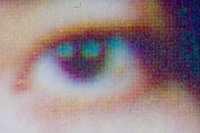
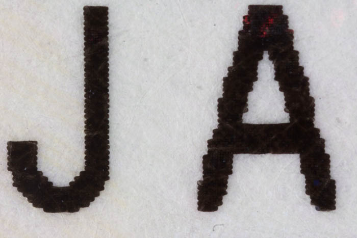
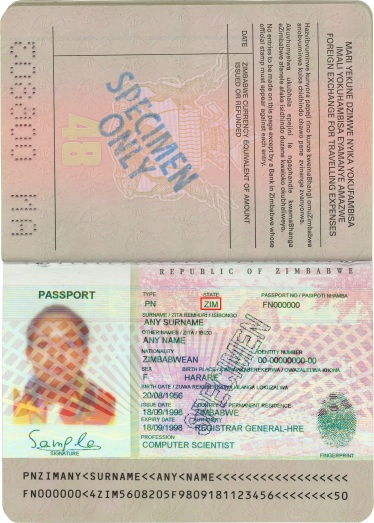
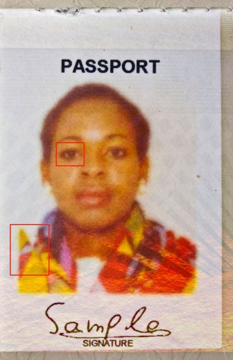
Fig. 6. Zimbabwe. Passport: |
||

a |
b |
c |
|
Fig. 7. Nigeria. Driver license: |
||
A form, a material and a structural design of a document. There are following types of a document according to these characteristics: a passport book, a sheet document, a booklet, a card.
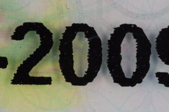
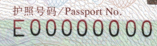
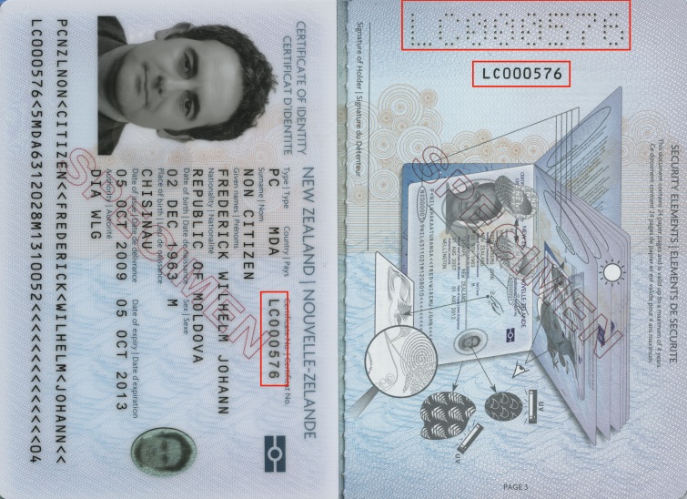
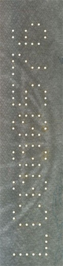
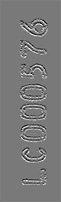
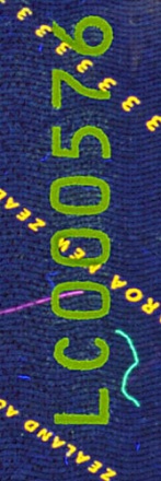
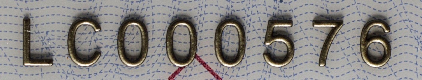
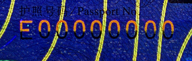
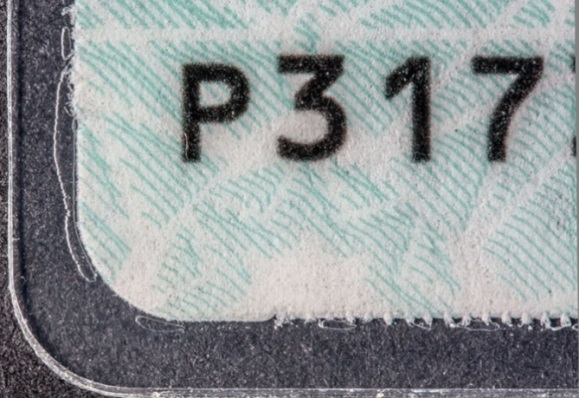
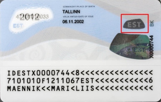
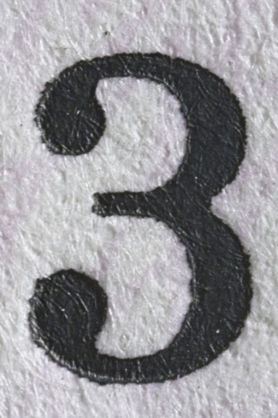
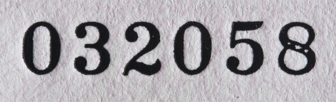
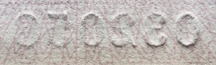
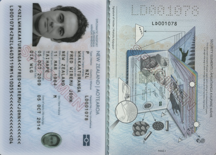
A unique combination of letters and (or) numbers which is assigned to any document. A document number is applied by laser engraving (fig. 2e), letterpress (fig. 1), printer, perforation (fig. 2b). An ink which is used for printing of a document number may luminescence in UV and IR-light and have magnetic (fig. 2c) or other features. Special fonts and numbering devices are used for applying document numbers. Different information can be encoded in a document number.

a |
b
c |
||
|
Fig. 1. China. Passport: |
|||
a |
b |
c |
d |
e |
|||
|
Fig. 2. New Zealand. Passport: |
|||
The process whereby a variable data incorporated into a document. The data allows identifying the document and its holder and verifying whether the document belongs to the holder. According to the way of personalization the data can be read and proceeded both manually and automatically with the help of special scanners, card-readers, etc.
The personal data is applied by laser perforation, laser engraving, or with the help of a printer.
ELECTRONIC DOCUMENT (E-PASSPORT)
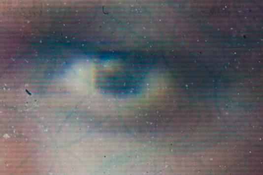
A document in the form of a book or a card with an electronic chip and an antenna. A microchip contains scrambled holder’s personal data: digital photo, name, data from a machine-readable zone, fingerprints and iris, etc. This data is read by special devices and compared to document personalization data, holder’s physical data and the database. Documents with bio data usually have special mark (fig. 1).
 |
|
Fig. 1. Azerbaijan. Passport. |
An element of a document construction in the form of a paper sheet which stitches a book block and inside cover (fig. 1).
Types of endpapers in travel documents:
- front endpaper (an inner side of the front cover sheet);
- back endpaper (an inner side of the back cover sheet).
Endpapers are usually made of a special security paper which differs from inner paper sheets in order to prevent partial document forgery (book block unstitching and sheet replacement). A holder’s data is usually placed on back endpapers.

a |
b |

c |

d |
|
Fig. 1. Endpaper: |
|
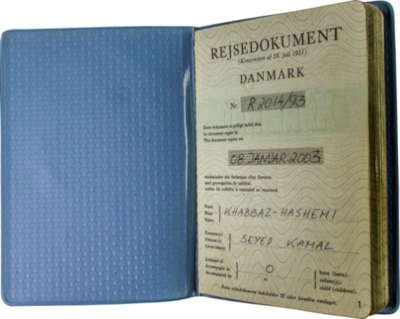
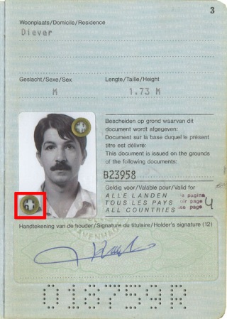
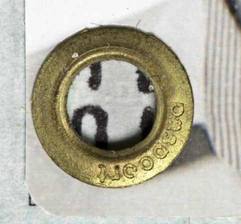
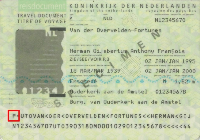
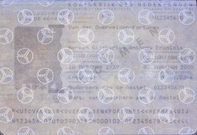
A fixing method which is applied for connection of flat details, for example, a holder’s portrait and a passport page by using a tube section with the flared head (fig. 1).
a |
b |
c |
|
Fig. 1. Netherlands. Travel document. Convention of 1951: |
||
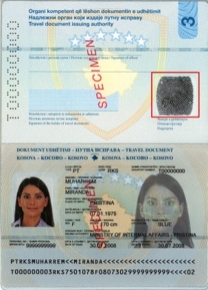
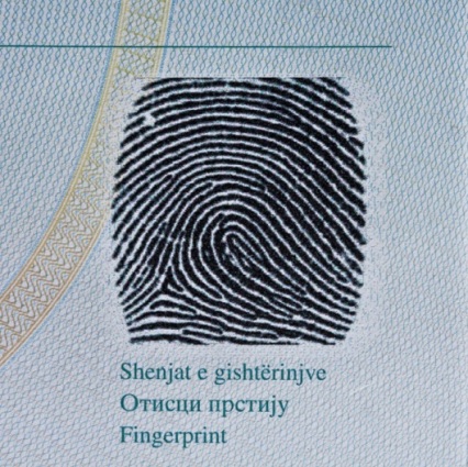
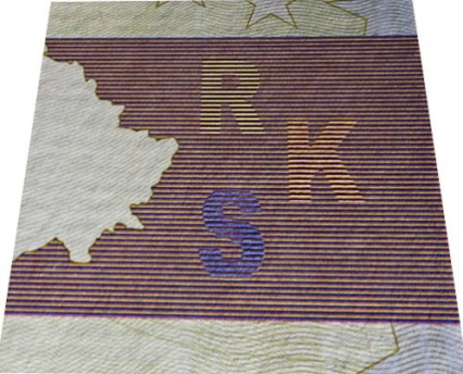
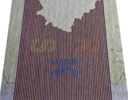
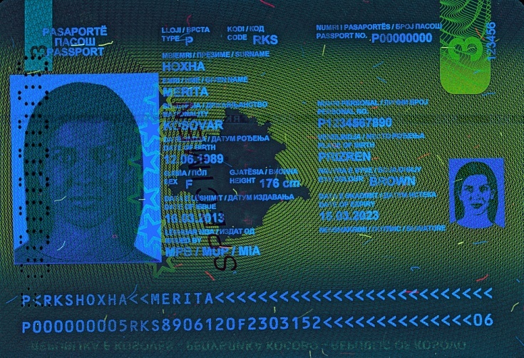
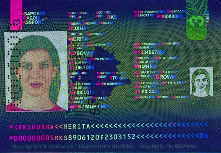
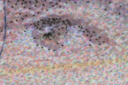
A visible graphic reproduction of a holder’s fingerprint uppermost layer (fig. 1). It is a relief lines (papillary pictures). Their structure is determined by a number of friction ridges divided by grooves. These friction ridges form a complex skin pattern which has the following characteristics:
- individuality — a structure of papillary ridges is individual by its location, configuration and mutual arrangement. They form a special pattern which is unique for every person;
- relative stability — permanent structure of the uppermost skin layer which remains unchanged throughout the life;
- ability to recover — After the skin damage papillary ridges recover to the initial state.
Fingerprint identification is the most common, effective and reliable biometric technology.
a |
b |
c |
|
Fig. 1. Kosovo. Passport: |
||
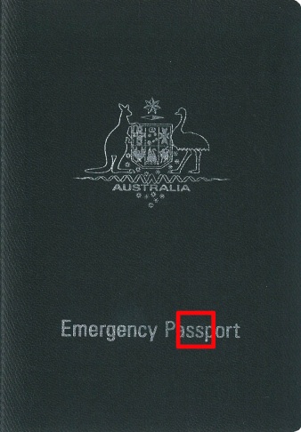
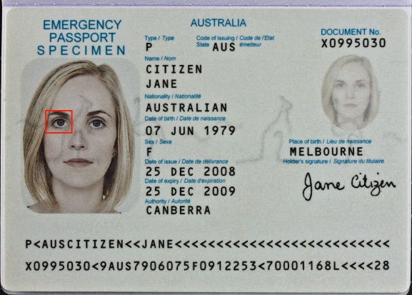
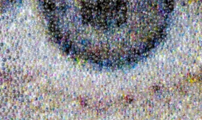
Optically variable element visually perceived as an image hovering or floating in space above or below the document surface.
Characteristic features of the floating image:
- the effect of floating in space emerges when the image is viewed at a right angle and disappears when viewed at an acute angle;
- the kinetic effect is perceived as a slight movement of the image together with the observer when the viewpoint is changed.
The effect of floating images is achieved due to multilayer cell-structured laminate which consists of an array of spherical diverging and converging microlenses. According to the laws of geometrical optics, microlenses produce false images which are perceived by the human eye as floating above or below the document surface.
Retroreflective effect characterized by bright luminescence and color changing is observed when color images are viewed in coaxial light.
|
|
The effect of floating images. Scheme |
|
a |
b |
c |
|
Australia. Emergency passport (2014): |
||
|
d |
e |
f |
|
Australia. Diplomatic passport (2014): |
||

g |

h |
|
Australia. Diplomatic passport (2014): |
|
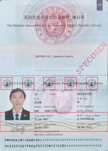
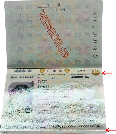
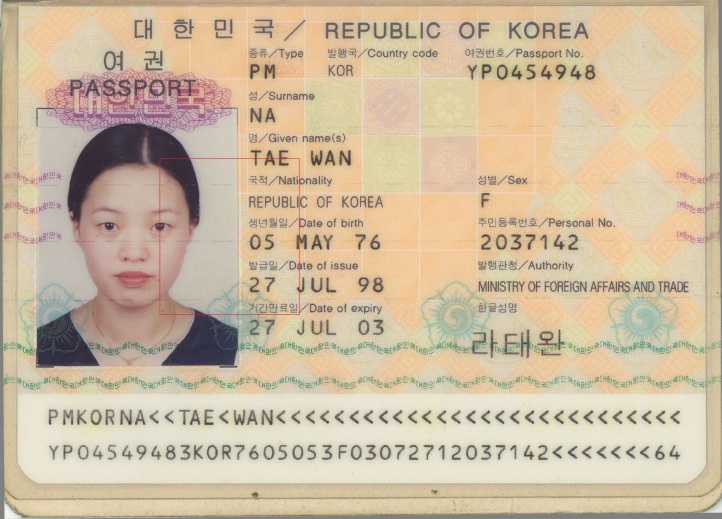
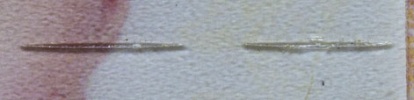
An image is applied to a paper, carton or polymer material by stamping a foil by means of heat. Due to high pressure, parts of the foil get into the paper making its mechanical separation practically impossible (fig. 1, 2).
a |
b |
|
c |
||
|
Fig. 1. Korea. Passport: |
||
a |
b |
c |
d |
e |
f |
||
|
Fig. 2. Foil stamping: |
|||
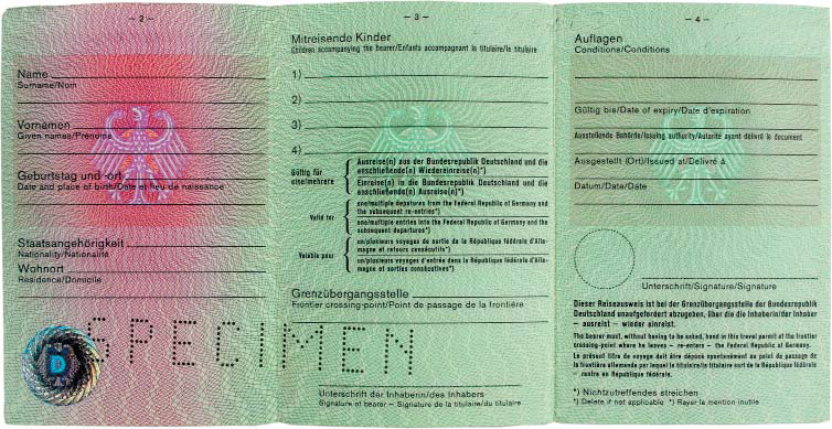
A type of a document construction in the form of a sheet folded once or several times.
 |
|
Fig. 1. Austria. Driver’s license. |

a |
b |
|
Fig. 2. Germany. Travel document instead of a passport: |
|
 |
|
Fig. 3. Austria. Registration certificate. |
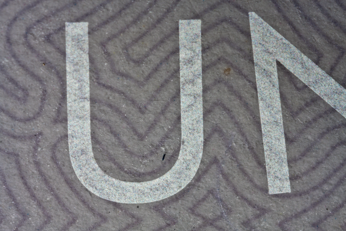
An image formed during the manufacturing process of the matte laminating film (heated roll lamination) by means of temperature and pressure. Visible under oblique light and has glossy effect. Glossy laminate overprint is invisible in normal light at a right angle.

a |
b |
|
Fig. 1. The United Arab Emirates. Temporary passport: |
|
A printing technique which uses printing plates where printing elements are recessed as compared with spacing elements. Printing elements are in the form of small raster cells separated by thin dividers. A printing plate is produced on a metal cylinder. During the printing process a low-viscosity ink is applied in plenty over the whole surface of the rotating plate, then a special knife (scraper) removes the ink totally from spacing elements and its excess from printing elements. The ink is transferred to the substrate under the contact pressure. This technique is used for printing on different substrates (fig. 1, 2).
Special features of the print:
- absence of sharp contours and lines;
- raster lines of spacing elements are visible in the areas of light halftones;
- absence of relief;
- notched edge of an image (fig. 1c, 2b).

a |
b |
c |
|
|
Fig. 1. Latvia. Passport: |
|
a |
b |
c |
|
Fig. 2. Azerbaijan. Passport. 2008: |
||
A graphic element in the form of a complex geometrical pattern of repeated thin curved lines formed according to certain mathematical rules. Guilloche elements form rosettes, frames, borders, vignettes and elements of a security pattern. Guilloche lines can be both positive and negative (fig. 1).
a |

b |
|
Fig. 1. Russia. Diplomatic passport: |
|
Intaglio and offset printing are used for printing guilloche patterns (fig. 2, 3).
a |
b |
|
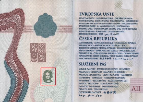
Fig. 2. Czech Republic. Diplomatic passport: |
|
a |
|
b |
c |
|
Fig. 3. Czech Republic. Diplomatic passport: |
|
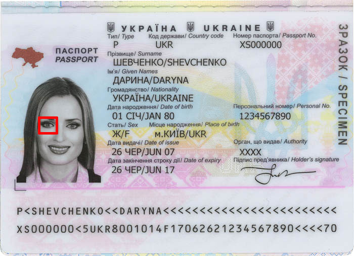
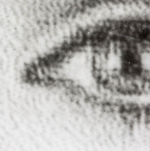
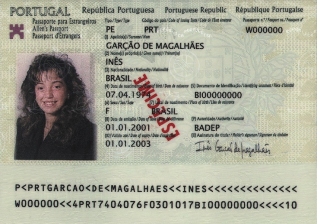
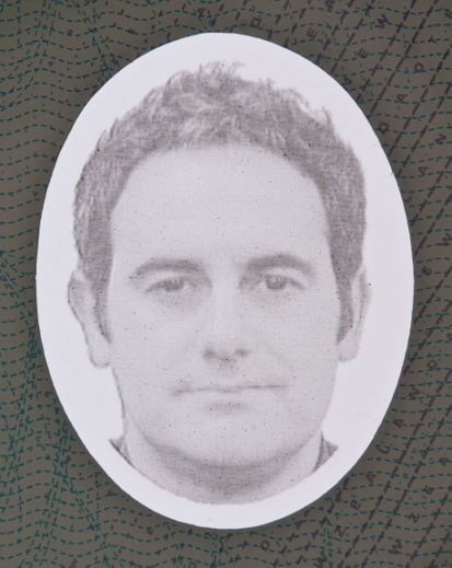
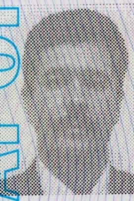
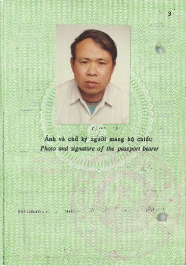
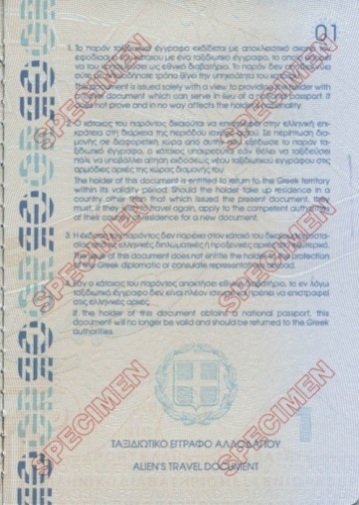
An image formed by taking a photo of a holder’s face. It is printed by laser engraving (fig. 1), photographic process on the photographic paper or a printer (fig. 2). A holder’s portrait is applied directly to the substrate (integrated photo) (fig. 1, 2), stuck, stapled or fixed on a data page using rivets. Sometimes it is additionally binded by the wet or dry (relief) stamp.
a |
b |
|
Fig. 1. Ukraine. Passport: |
|
a |

b |
c |
|
Fig. 2. Portugal. Alien’s passport: |
||
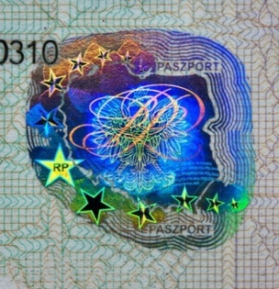
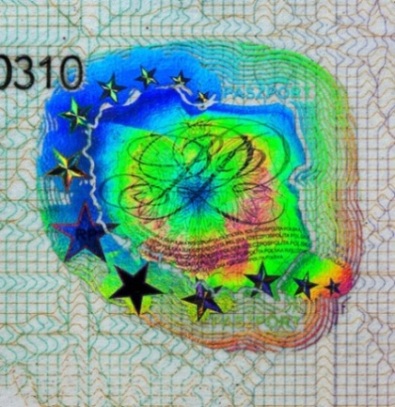
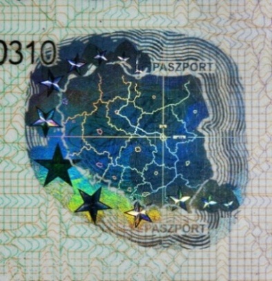
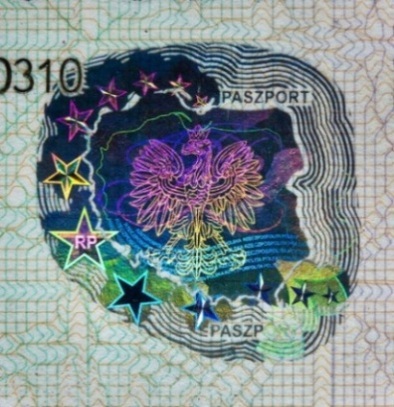
A diffractive optically variable device which contains an image applied by the holographic method. A holographic image changes at different angles of observation and illumination. As a rule, a hologram has a diffraction grating density of more than 5000 stripes per 1mm and a reflection layer. When white light beams reflect from a reflection layer and then diffract from a diffraction grating a hologram becomes iridescent (fig. 1).

Fig. 1. Structure of a sticker hologram on a polyester substrate: |
Hologram classification:
By optical properties:
- reflection hologram forms an image in reflected light. Aluminum foil or a transparent dielectric which reflects not more than 10-20% of light (transparent hologram) are used as a reflection layer;
- transmission hologram forms an image in transmitted light and visualized against the light.
By manufacturing method:
- analog hologram — a holographic image is applied by a laser which generates beams with a wavelength equal to the wavelength of light;
- digital (Dot-matrix) hologram — a holographic image is created by means of a computer and applied in the form of raster dots placed in one plane. Every dot (pixel) is a diffraction grating;
- electron-beam (E-beam) hologram — a holographic image is applied using the electron-beam lithography system which creates a diffraction grating with the help of the electron beam;
- combined hologram — elements of a hologram are applied using different methods (analog and digital) and joined with high accuracy
By visual elements of design:
- 2D-3D holograms — plane images (2D part) lie at different visual depth (3D part);
- kinegram — a motion effect of contour images, a change of their size and shape at different angles of observation;
- multi-channel hologram — a hologram image with a switch effect. Completely different scenes can be observed on the same hologram after changing the angle of observation (fig. 2e, f).
Identity documents contain holograms with special security features:
- microprinting, microtext (fig. 2b) with letter height of 30 mcm or higher;
- latent scrambled images visualized by the devices which form a special laser beam;
- отсутствие красочного рельефа;
- laser demetalization and numbering.
a |
b |
c |
d |
e |
f |
|
Fig. 2. Poland. Diplomatic passport: |
|
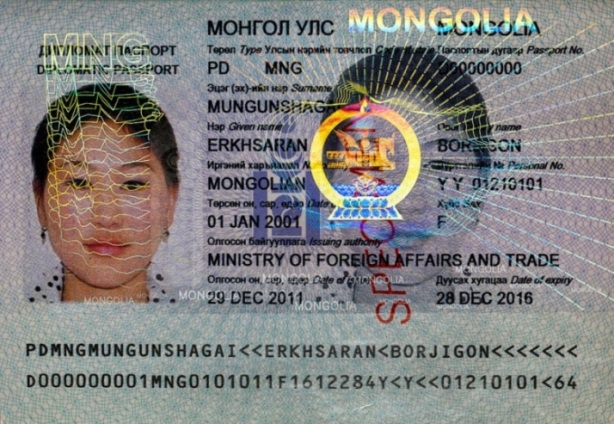
Fig. 3. Mongolia. Diplomatic passport. |
|
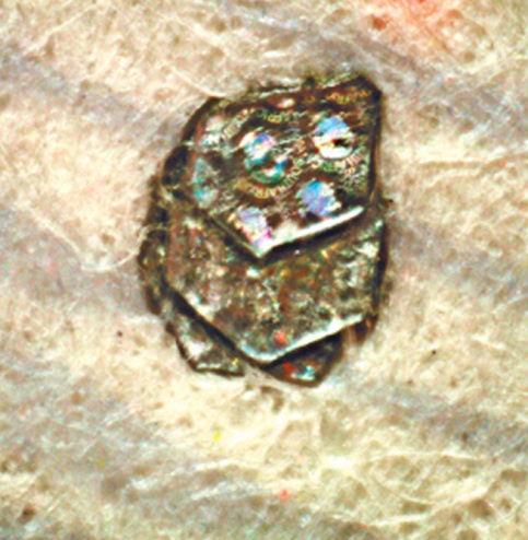
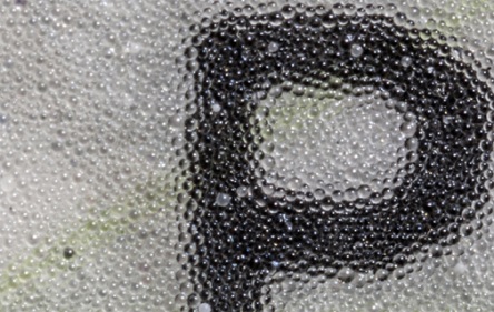
HOLOGRAPHIC MICROPARTICLES OVDot
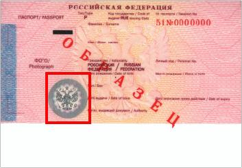
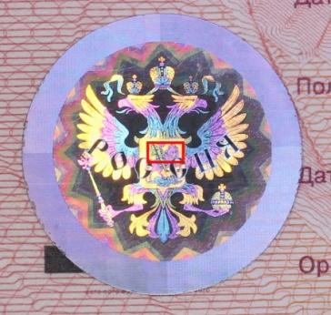
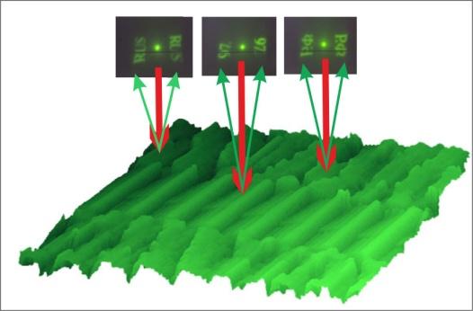
Faceted metallic particles with the size of 100-600 mcm which are randomly embedded in a substrate all over a document page. Holograms are applied over the surface of microparticles by the electron-beam lithography method and contain a nanoimage or a nanotext. Magnification mode shows how elements of a holographic image change their color at different angles of illumination and observation (fig. 1).
a |
b |

c |
|
Fig. 1. South Africa. Passport: |
||
Main definitions and terms:
- pivot point — a point which is located on the surface of the object (document) and identified as a center when describing its characteristics;
- axis of illumination — a line connecting the light source and the pivot point of an object;
- axis of observation — a line connecting the optical system of the observer’s eye and the pivot point of an object;
- angle of illumination — an angle between the axis of illumination and the object surface;
- angle of observation — an angle between the axis of observation and the object surface.
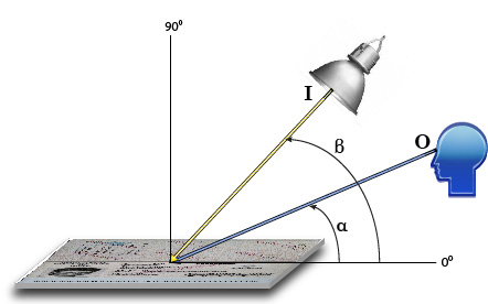
Fig. 1. Goniometric scheme of illumination and observation: |
Types of illumination classified by light spectrum:
- ultraviolet light — UVA (320–400 nm), UVB (290–320 nm), UVC (200–290 nm);
- white light — visible light with the wavelength of 380–780 nm;
- infrared light— IR (740–1500 nm).
| Colour | Wavelength range, nm |
| Violet | 380—440 |
| Indigo | 440—485 |
| Blue | 485—500 |
| Green | 500—565 |
| Yellow | 565—590 |
| Orange | 590—625 |
| Red | 625—740 |
| Fig. 2. Wavelength range of visible (white) light with spectral colour marks | |
Direction (Azimuth) of light:
- front lighting is directed from the observer’s side towards the X-axis;
- back lighting is directed from behind the object towards the X-axis;
- side lighting is directed from the right or left sides of the object towards the Y-axis.
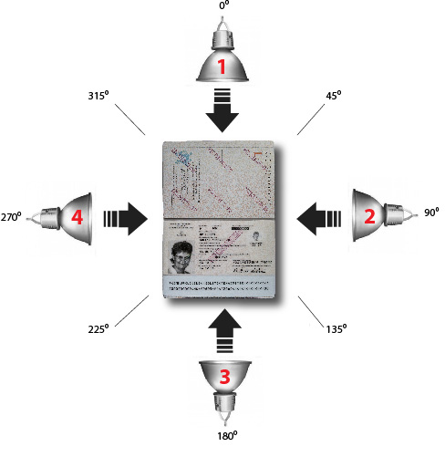
Fig. 3. Illumination. View in a horizontal axis: |
Types of illumination classified by the angle of light incidence:
- sliding light (0–30⁰) is used for visualization of relief details of a surface;
- oblique light (30–60⁰);
- incident light (60–90⁰);
- bottom light is used for visualization of images in transmitted light.
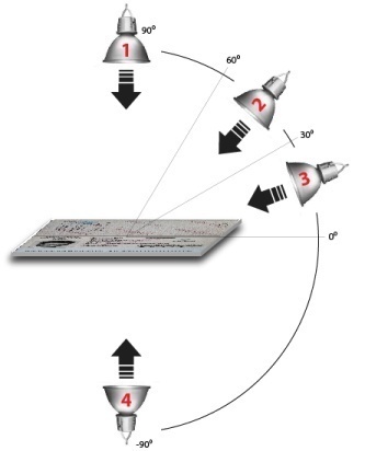
Fig. 4. Illumination. View in a vertical axis: |
Types of illumination classified by a light flow:
- spot light is a harsh, direct light which creates visible shadows on the object and reflections on the illuminated surface;
- soft light is an indirect light which creates smooth light shadows and hide relief details of objects.
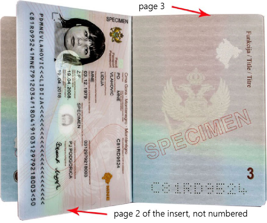
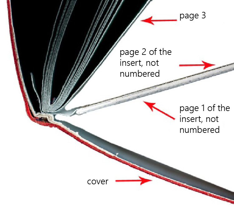
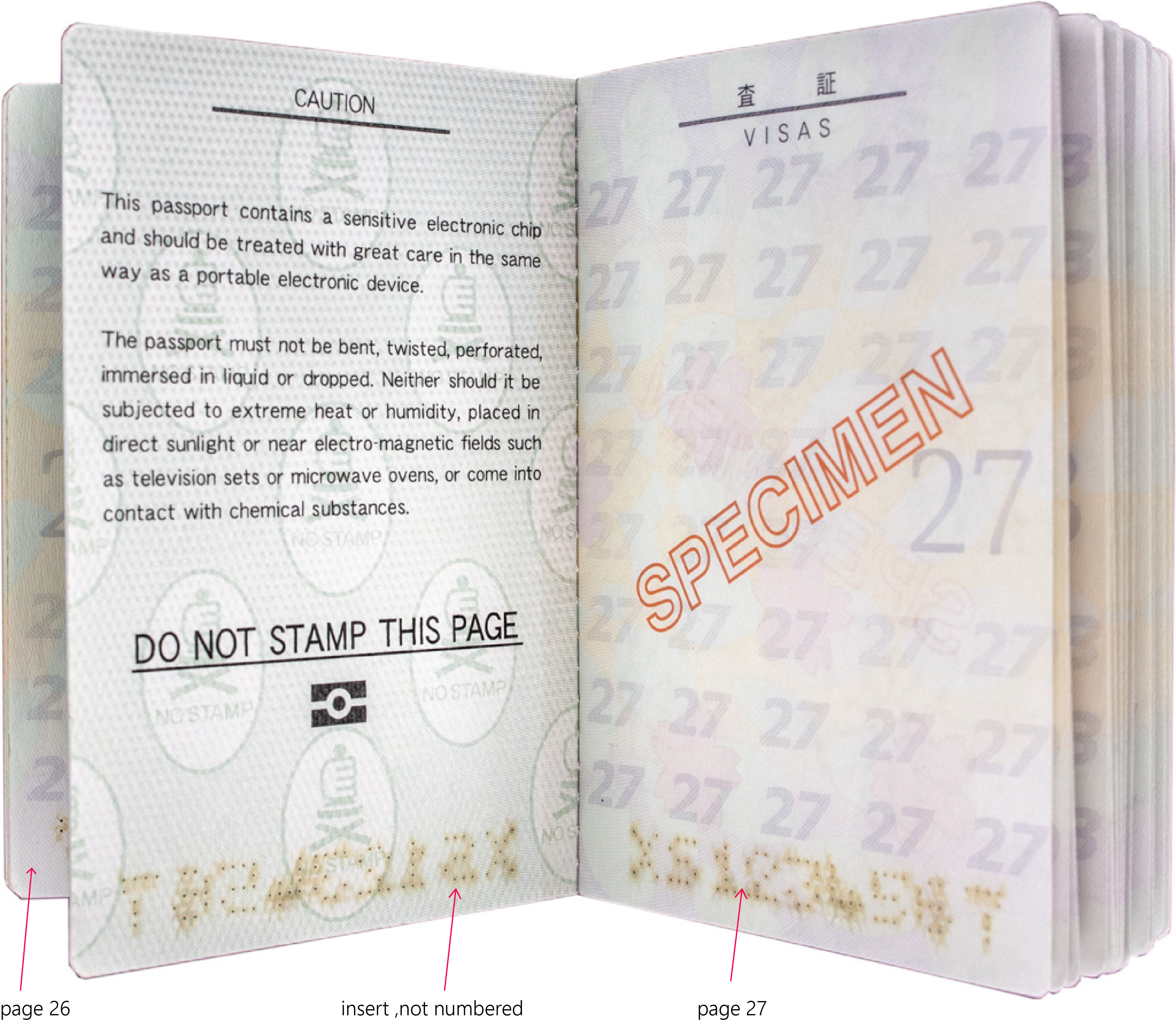
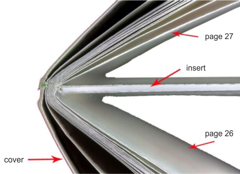
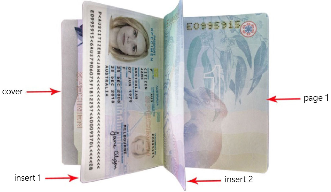
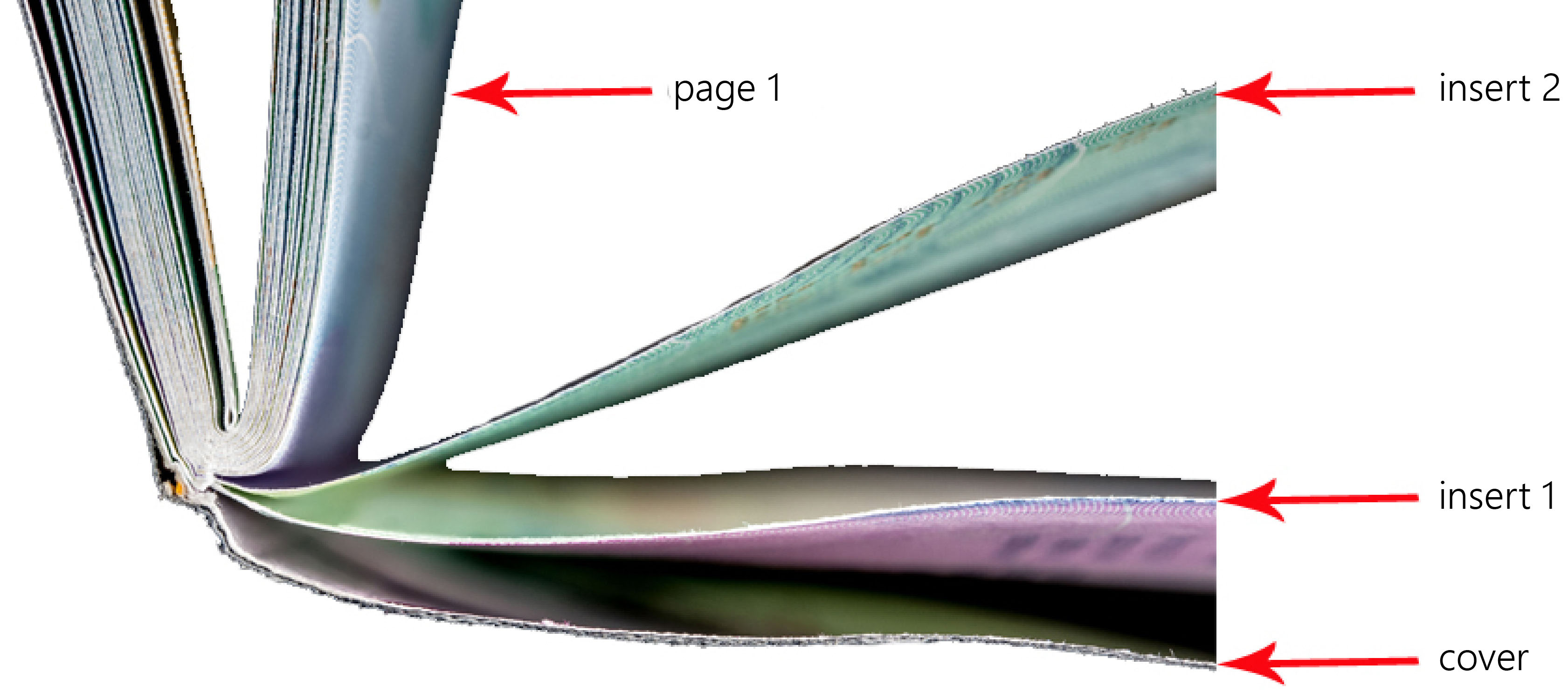
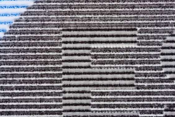
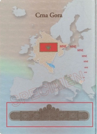
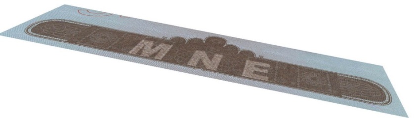
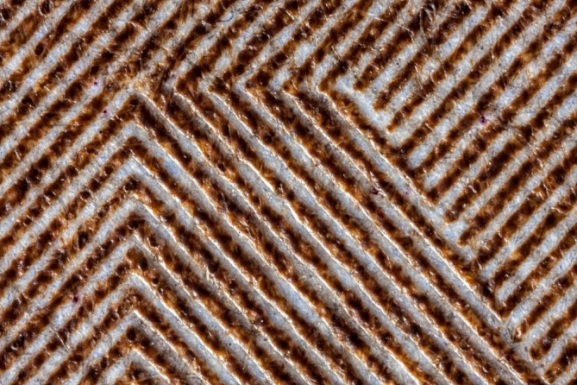
An additional element of a book block in the form of a separate sheet with numbered or unnumbered pages which may not be included in general numbering (fig. 1, 2). Material and method of fixing an insert may differ from typical pages of a document. One document can contain more than one insert (fig. 3).
Types of inserts:
- multilayer integrated card with holder’s data (fig. 1)
a |
b |
|
Fig. 1. Montenegro. Diplomatic passport. |
|
- multilayer polycarbonate sheet with an RFID chip (fig. 2)
а |
б |
|
Fig. 2. Japan. Passport. |
|
- paper sheet with or without lamination (fig. 3)
a |
b |
|
Fig. 3. Australia. Passport. |
|
- transparent polycarbonate sheet with a verification filter and a secondary holder’s image (fig. 4).
а |
|
Fig. 4. Belgium. Passport. |
A printing method from a plate where printing elements are located below spacing ones. Printing elements are applied by engraving or etching. The printing process is carried out using a high-viscosity ink. An ink fills in the recessed areas of the printing plate and is transferred to the substrate under high pressure. The significant deformation of a paper substrate is observed.
Characteristic features of prints:
- thick ink layer produces a tactile relief (fig. 1b, 2b);
- concave from the reverse side of a print is clearly visible on a paper substrate (fig. 1d);
- ink creeping at strokes edges of graphic elements (fig. 1b).
a |

b |
c |
d |
|
Fig. 1. Norway. Diplomatic passport: |
|
a |
b |
|
Fig. 2. Switzerland. Diplomatic passport: |
|
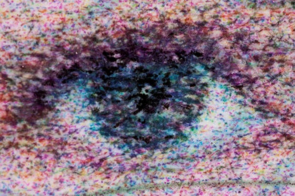
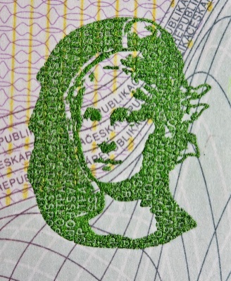
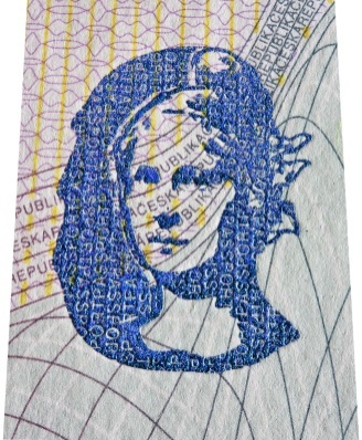
IPI – Invisible Personal Information
IPI™ is the #1 graphical security for personal documents. This technology encodes personal data (name, numbers etc.) in the portrait. IPI™ directly links the photograph both to the document holder and the document. Personal data is invisible to the human eye; the authorized persons can easily verify the authenticity with a dedicated decoding lens.
IPI™ can be authenticated with electronic passport-readers as well.
The implementation of IPI™ started two decades ago. Nowadays several dozens of countries use IPI™ feature, both in passports and ID-1 format government credentials.
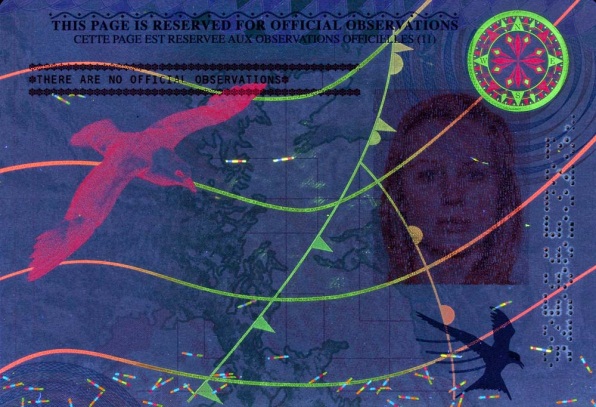
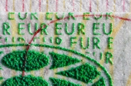
IR-FLUORESCENT INKS
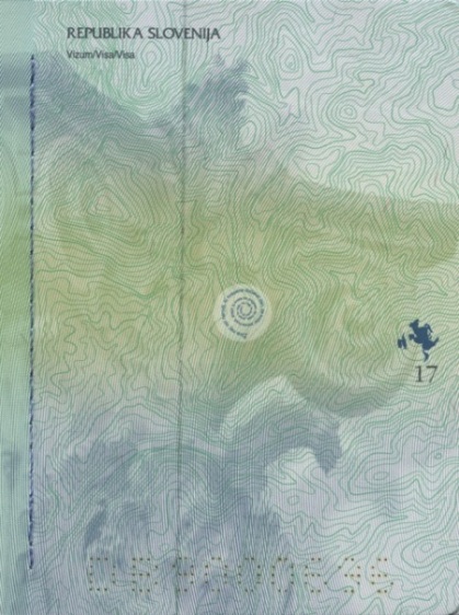
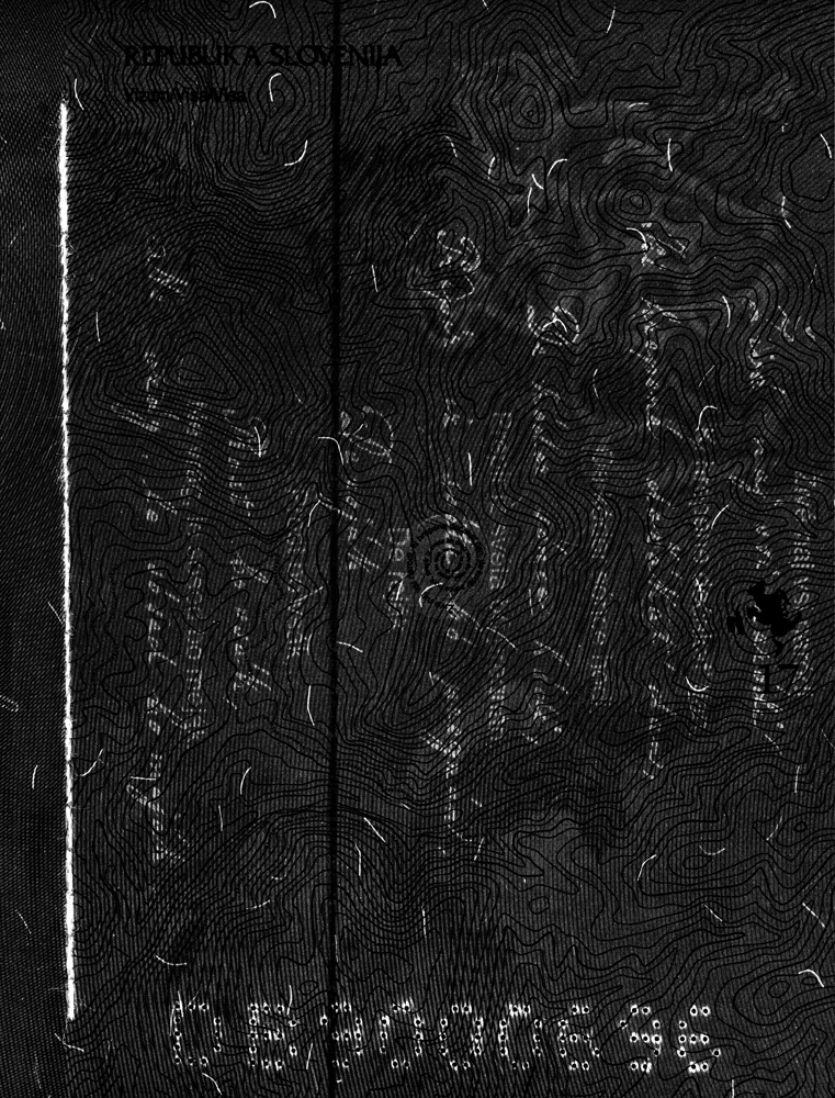
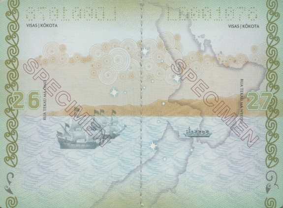
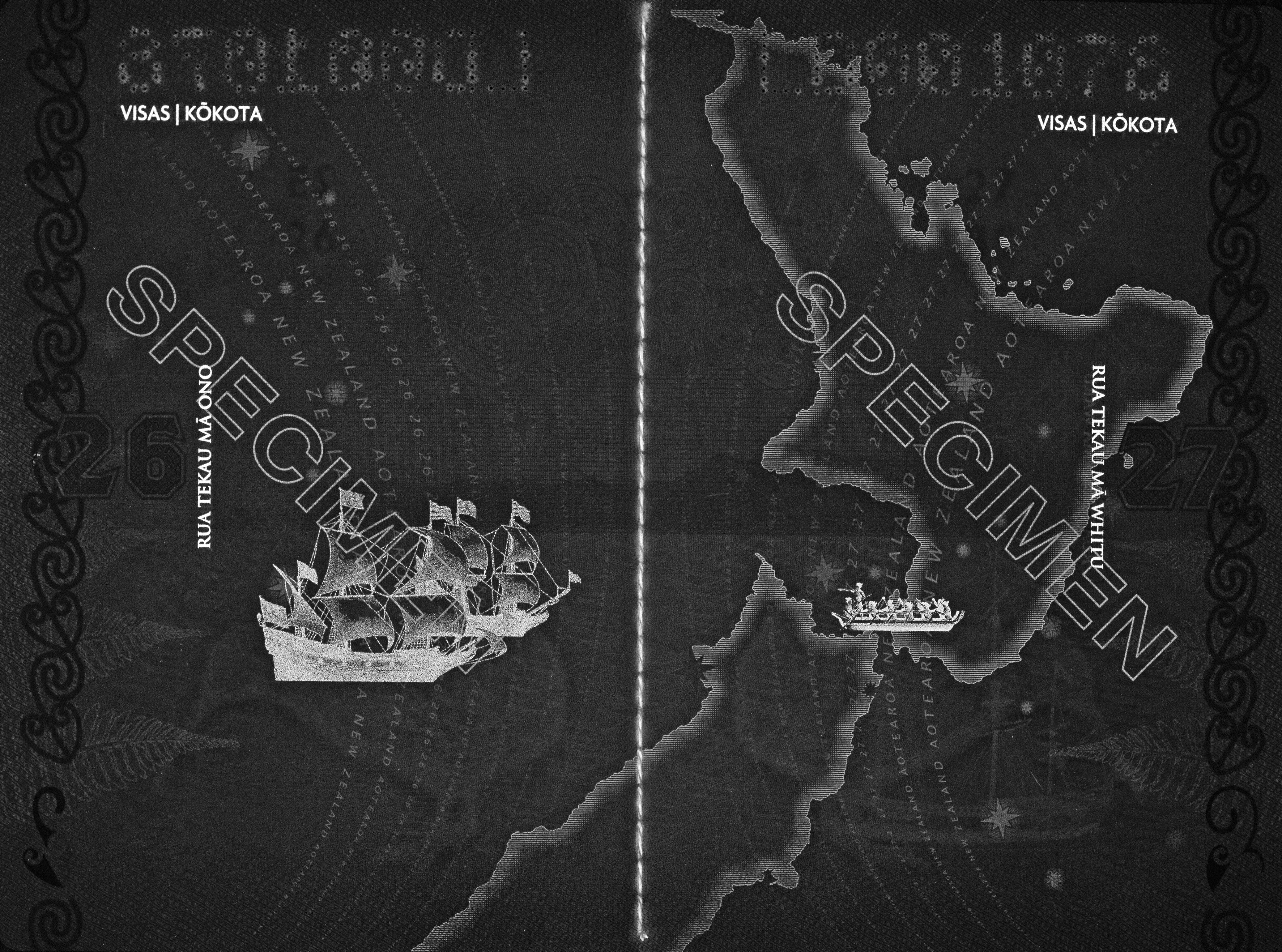
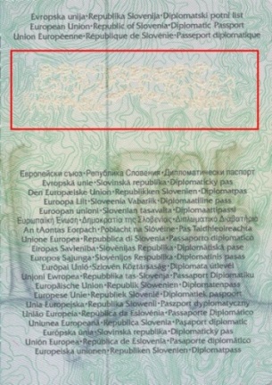
Inks containing fluorescent pigments which glow when exposed to blue-green light of 400-530 nm. Luminescence is visible under IR-light of 850-950 nm as bright light images on a dark background (fig.1, 2). IR-fluorescent inks are not perceived with the naked eye in white light. Inks are used for applying design elements, texts or for coloring security fibres, a security thread, a stitching thread, etc.
a |
b |
|
Fig. 1. Slovenia. Diplomatic passport: |
|
a |
b |
|
Fig. 2. New Zealand. Diplomatic passport: |
|
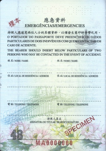
Inks which have similar spectral features in visible light (perceived like of the same color) but different under IR-illumination (some inks absorb IR-light others reflect). As a result, when examining an image with IR-metameric inks only IR-visible parts of the image can be seen on the monitor (fig. 1).
Infrared security features are based on the property of a document material (usually dyes) to absorb or reflect IR-light in different ways. An IR-map of a document is a grayscale image of the document under IR-light of 850-950 nm wavelength. Depending on the level of absorption or reflection the image on the map may be black, gray or invisible (fig. 2, 3).
a |
b |
|
Fig. 1. Brunei. Passport: |
|
a |
b |
a |

b |
|
Fig. 2. Macau. Passport: |
Fig. 3. Belgium. Passport: |
||
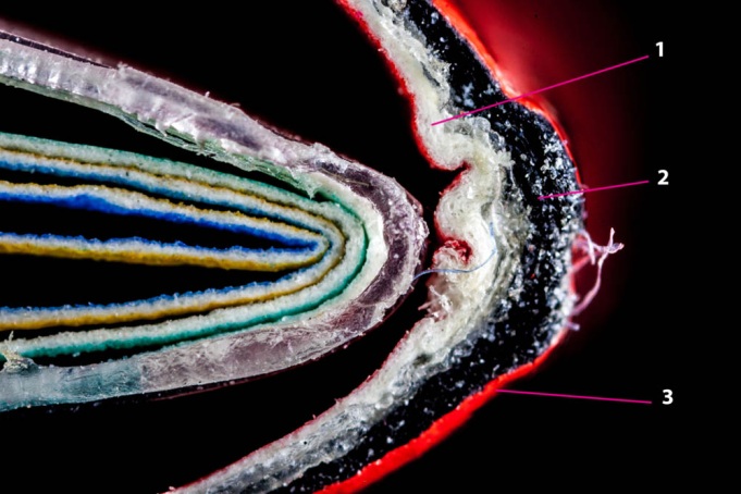
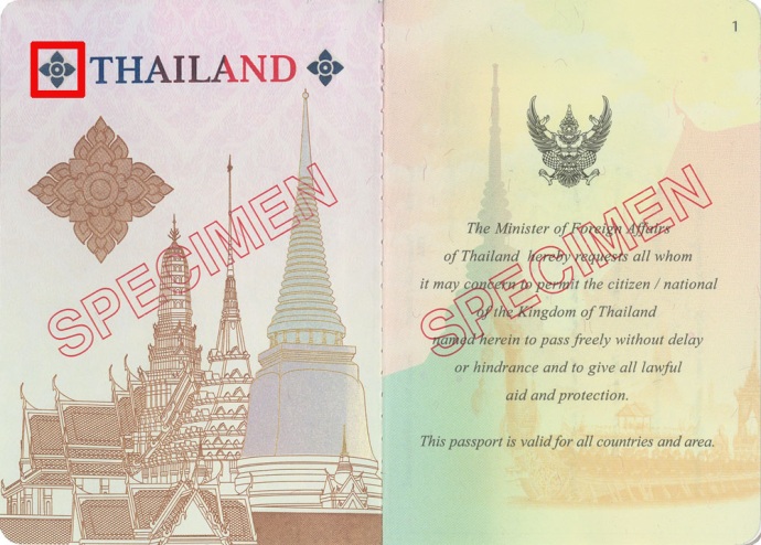
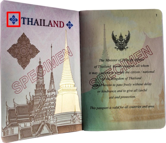
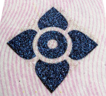
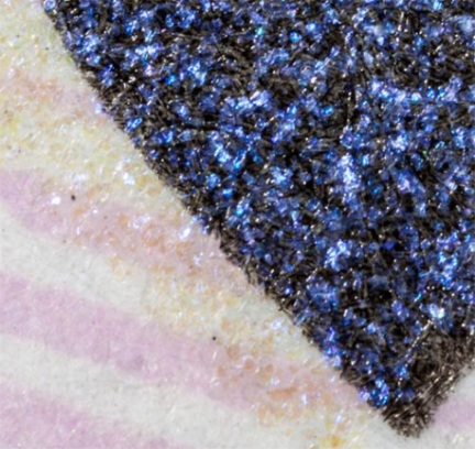
A semi-transparent ink with a pearl luster determined by an interference structure of a thin film. The ink contains mica scaled pigments covered by TiO2, Fe2O3 or other metal oxides placed in the transparent binding medium of the ink (fig. 1).

Fig.1. Structure of an iridescent ink pigment |
When falling on pigment scales, a part of light reflects and another part transmits into multilayer scales. As a result multiple reflection and transmission of light by different layers occur and we may observe interference.
A color depends on the thickness of the oxide layer. Brightness and blinking effect are determined by the size of pigments. If the background color is dark and rich it also affects the ink tone. The luster is not seen at a right angle but a sparkle, a slight change of the ink tone or its brightness are observed when changing the angle of observation or illumination (fig. 2).
a |
b |
c |
d |
|
Fig. 2. Thailand. Temporary passport: |
|
A thin-film coating in the form of a stripe, a text or an image with color changing effect. The effect appears when the angle of observation or illumination changes. The iridescent laminate doesn’t contain ink pigments. It is transparent when viewed at a right angle in diffuse white light. The coating is red under direct incident light at a right angle and becomes green when viewed under oblique light at an acute angle (fig. 1, 2).
An even change of the angle of illumination and observation leads to a color change into medium compound spectral tones. A color changing effect is determined by a thin-film interference.
The iridescent laminate is applied on the inner surface of the laminate on the data page.

Fig. 1. Thin-film interference scheme |
a |
b
c |
d |
e |
|
Fig. 2. Sweden. Official passport: |
|
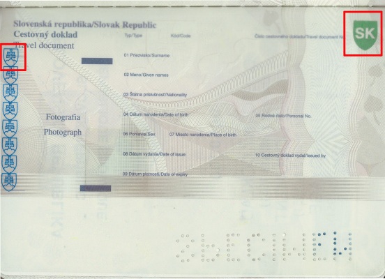
A transparent polymer film applied on the substrate over the whole data page or only over its part in order to protect the document against its damage or forgery.
Laminate classification
By surface texture:
- glossy (fig. 3b);
- matt (fig. 1);
- porous (fig. 2).
By fixing method:
- stitched into a passport book (fig. 3);
- not stitched into a passport book (fig. 4).
A laminate can cover a page both from one and two sides. In the second case laminate sheets are solded together in the form of a pocket (fig. 1b). The laminate may have right or rounded angles. It can also incorporate additional security features such as holograms, retroreflective effect, embossing, etc.
a |
b |
|
Fig. 1. Azerbaijan. Passport: |
|
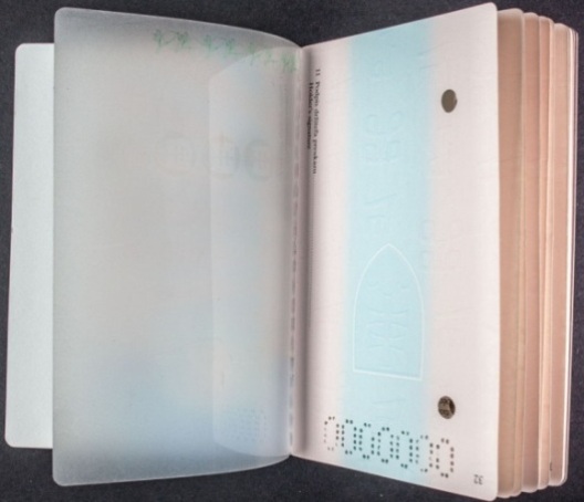
Fig. 2. Slovakia. Identity card as a travel document. |
|
a |
b |
|
Fig. 3. Australia. Temporary passport: |
|
a |
b |

c |

d |
|
Fig. 4. France. Passport: |
|
a |

b |
|
Fig. 5 Japan. Passport. 2013: |
|
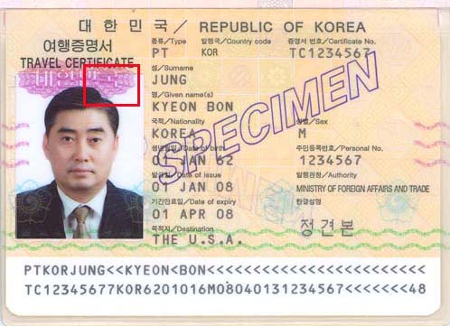
An image which is applied on the laminate coating to protect it against forgery. Screen printing and gravure printing are the most frequent printing methods used for the laminate overprint (fig. 1).
a |
b |
|
Fig. 1. Korea. Travel document: |
|
Applying an image or a text on a paper or a polymer substrate using the energy of a laser beam. A laser beam heats the surface of a substrate (for example, polycarbonate). As a result carbon deposition occurs in the upper transparent layers. Deposing carbon is visualized in the form of black dots of different tones which form an image. When the laser beam affects a paper surface its discoloration occurs and the ink layer is removed.
Classification
By technology:
- removal of a previously applied layer, for example, an ink (fig. 1, 2);
- removal of the material (appearing of a cut or a trough in the place of a laser beam exposure) (fig. 3b).
By image view:
- monochrome laser engraving occurs when the laser source has no ability to control power (fig. 3c);
- tonal laser engraving is applied in the greyscale by controlling power and speed of the beam (fig. 4b).
By image type:
- vector laser engraving occurs when the laser outlines letters or image contours with thin lines (fig. 3b);
- raster laser engraving takes place when the laser forms a number of different density dots (fig. 4b).
By volume:
- plain (2D) laser engraving is applied on materials with a nontransparent surface (fig. 4c);
- volume (3D) laser engraving is tactile (fig. 4d).
Laser engraving is used in the personalization process for applying a holder’s portrait or personal data, numbers or other security features.
a |
b |
|
Fig. 1. Slovenia. Diplomatic passport: |
|
a |
b
c |
|
Fig. 2. Egypt. Passport: |
|
a |

b
c |
|
Fig. 3. Hungary. Passport: |
|
a |
b |
c |

d |
|
Fig. 4. Montenegro. Passport: |
|
LFI — Latent Filter Image
An image which is applied by the slit raster technology. The scene of the image changes when changing the angle of observation. A latent filter image consists of a slit raster printed inside a transparent polycarbonate which serves as an optical filter and a scrambled image stripped from two initial images (fig. 1). Lightness of the image changes regarding to the background when changing the angle of observation. Latent (second) image is visualized at an acute angle of observation and printed by offset (fig. 2).

Fig. 1. Scheme of a latent filter image visualization: |
|
a |
|
b |
c |
d |
|
|
Fig. 2. Estonia. National identity card: |
|
(from German kippen — overturn, rotate)
An image formed by parallel straight relief strokes perpendicular to background strokes. The image is almost invisible in incidental white light at a right angle. It is visualized as an achromatic image in sliding white light at an acute angle of observation due to the shadow casted by relief strokes. A background and an image are applied by means of intaglio and are not differ in color and stroke density. An image becomes lighter or darker regarding the background when rotated around the vertical axis without changing the angle of observation (fig. 1).
a |
b
c |
d |
|
|
Fig. 1. Montenegro. Official passport: |
|
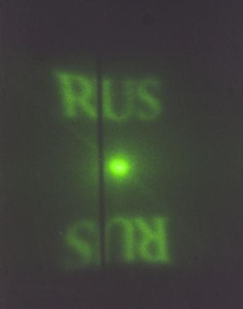
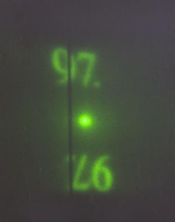
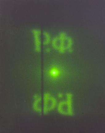
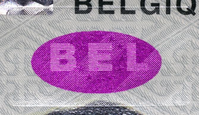
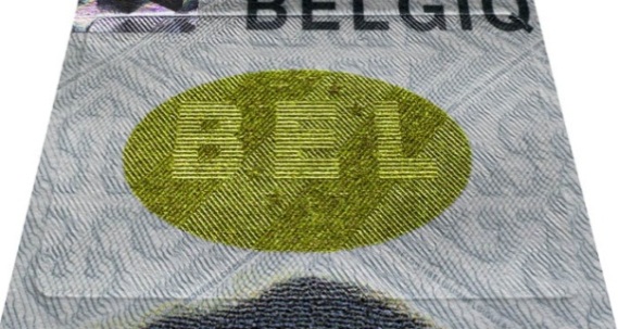
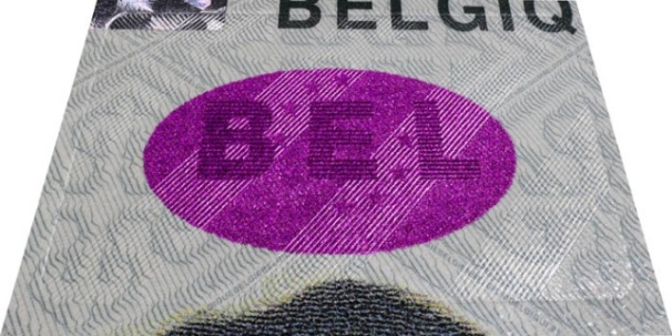
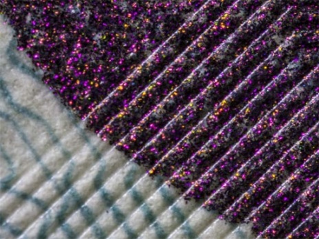
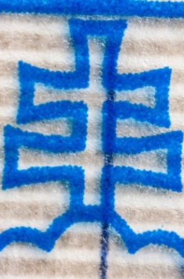
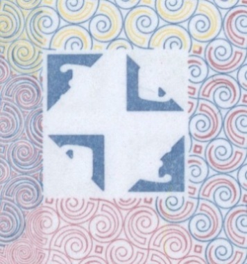
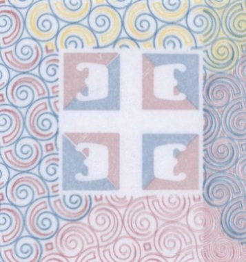
ИAn image in the form a number of lines or strokes of a certain geometrical shape or raster elements. A latent image makes a whole with the background image in technique, color and printing method. Its contours are slightly visible by the naked eye. Zoomed image is visualized as an alphabet symbol, figure or geometrical figure in white light (fig. 1). Latent image MASK is printed byoffset.
a |

b |
|
Fig. 1. Belgium. Passport: |
|
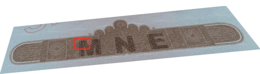
PEAK — Printed and Embossed Anti-Copy
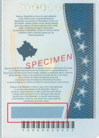
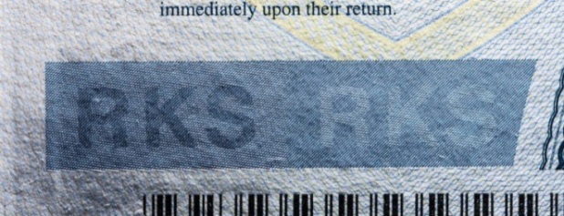
An image is formed by lines of blind embossing in the foreground and parallel straight strokes of the background. The image is almost invisible in incidental white light (fig. 1а). When sliding light is perpendicular to relief lines a shadow is formed and a latent image is visualized on the ridges of these lines (fig. 1b, 1c). When rotating a document around vertical and horizontal axes its different areas become lighter or darker regarding to the background (fig. 1d, e).
a |
b
c |
d |
e |
|
Fig. 1. Kosovo. Official passport: |
|
An image which is formed by parallel multicolor background strokes or relief lines of blind embossing. A latent multicolor image is slightly visible in white light. It is visualized as a chromatic image under oblique light. Every chromatic element of the image changes its color when rotating the document around the vertical axe without changing the angle of observation (fig. 1). Background strokes are applied by offset, relief lines are printed by intaglio.
a |
b |
c |
|
Fig. 1. Kosovo. Passport: |
||
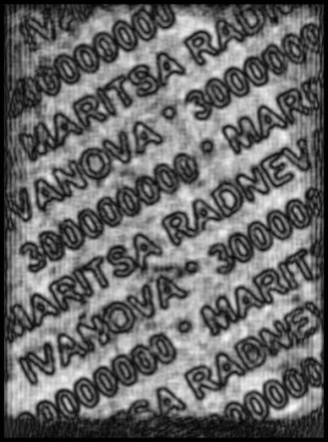
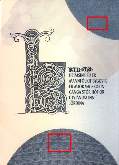
Strokes or raster elements of latent scrambled image are embedded in the background or a photo the way that the image is not visible when viewed by the naked eye. The image is previously fragmented and encoded according to special algorithms. A latent scrambled image is visualized by means of the lenticular decoding devices. It is applied by the printer or offset (fig. 1, 2).
a |
b |
|
Fig. 1. Bulgaria. Passport: |
|
a |
b
c |
|
Fig. 2. Iceland. Passport: |
|
(from Latin lenticula — a small lens)
A method of printing and visualization of an image using lenticular lens. It allows getting an image changing effect depending on the angle of observation. A lenticular is a sheet of a transparent plastic material. The front side of a sheet has a relief surface and composed of parallel cylindrical lenses. The back side is smooth. Scrambled interlaced images are printed under the lenticular. The principle of encoding is that initial images are stripped and joint together the way that at list two stripes (one from one image and the second from the other one) are placed under every lens. Every lenticular acts like a magnifier which zooms and reflects only one of all image stripes depending on the angle of observation. Achromatic or color scrambled images are applied using offset printing or laser engraving.

Fig. 1. Lenticular technology scheme: |

Fig. 2. Visualization of the image depending on the angle of observation: |
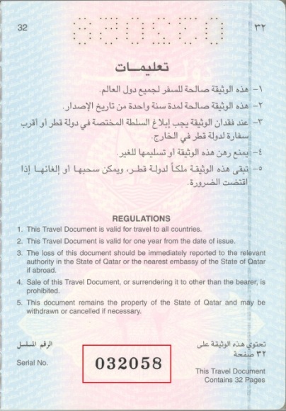
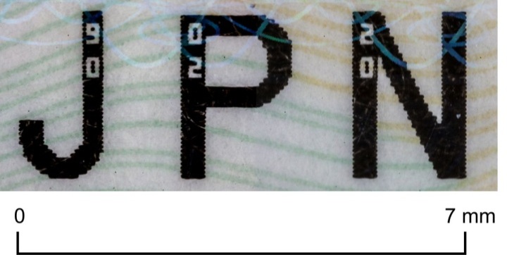
A printing technique when ink is applied to a substrate from a printing plate with printing elements raised above spacing elements. The process is carried out under high pressure (at least 15 kg/cm2) with the use of rapidly drying inks.
Characteristics of the print:
- uneven ink distribution in strokes: less ink in the middle than along the edges (fig. 1c);
- a rim formed by the ink along the edges of a stroke (fig. 1b);
- • substrate deformation: protuberance on the back side of a sheet and inward bulging on the front side of a sheet in the area where the print is applied (fig. 1d).
Letterpress printing is often used for printing serial numbers, bar codes, and design elements of covers.
a |
b |
|
c |
d |
|
|
Fig. 1. Qatar. Passport: |
||
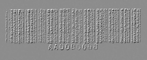
An ink containing ferromagnetic components, which have a specific reaction to the external magnetic field. Texts or symbols applied by the ink can be identified by special magnetic sensors or visualized by magneto-optic converters. The magnetic ink can be applied on security threads, fibres and used for printing images (fig. 1), serial numbers, bar-codes (fig. 2).
a |

b |
a
b |
|
|
Fig. 1. Sweden. Alien’s passport: |
Fig. 2. Azerbaijan. Small visa-sticker: |
||
A medium in the form of a stripe with the limited storage space. A magnetic stripe is usually placed at the reverse side of a card. The data which has previously been coded recorded on magnetic stripes. The data reading process is carried out by using special devices – readers (fig. 1).
 |
|
Fig. 1. The United States of America. Arizona. Identity card. |
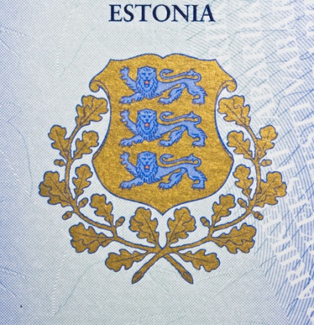
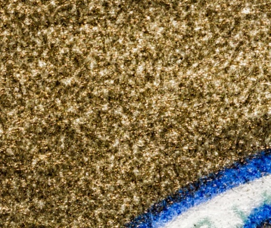
An ink containing a fine-dispersed powder of bronze (fig. 1b) and aluminum (fig. 2b). It has a specific metallic gloss. Only a gloss intensity changes when changing the angle of observation and illumination of the image applied by the metallic ink. Any significant changes in the color are not observed.
a |
b |
c |
|
Fig. 1. Estonia. Alien’s passport: |
||
a |
b |
c |
|
Fig. 2. New Zealand. Diplomatic passport: |
||
Special security inks (usually the pair of inks) which look similar in one type of illumination (for example, IR-light, UV light, oblique white light) but show a noticeable difference in another type of light.
a |
b |
|
Fig. 1. Japan. Passport: |
|
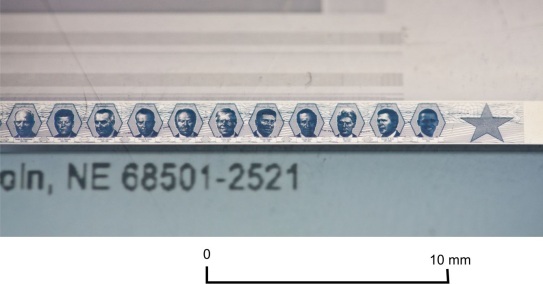
Micro images (figures, symbols, texts) of 0,15–0,3 mm height (fig. 1–5). Microprinting is visible only when zooming.
Microtext classification:
- positive (contour) microtext applied by dark letters on a light background (fig. 1b);
- negative (direct) microtext applied by light letters on a dark background (fig. 2b).
a |

b |
|
Fig. 1. Ukraine. Passport. Microtext: |
|
Microtext may be embedded into the image in the document, serve as a background, form patterns and images (fig. 3), increase security features of holograms (fig. 4), security threads, images applied with optically variable ink OVI.
a |
b |
|
Fig. 2. Japan. Passport. 2013: |
|
a |
b |
|
Fig. 3. Greece. Passport: |
|
a |
b |
|
Fig. 4. The United Arab Emirates. Official passport: |
|
a |
b |
c |
|
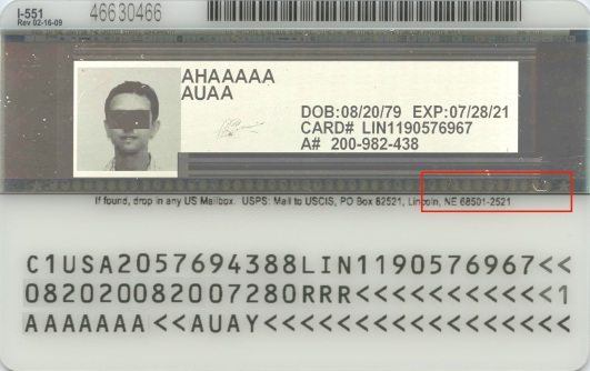
Fig. 5. The United States of America. Permanent resident card: |
||
MVC — Moire Variable Color
An image formed by parallel straight color strokes of the background and parallel lines of blind embossing located at an acute angle to one another. A background image is printed by offset. Blind embossing is applied by intaglio. The element looks monophonic at a right angle in incident light. Multicolor (rainbow) moire stripes appear when viewed at an acute angle under oblique light (fig. 1).
a |
b |
c |
d |
|
Fig. 1. Russia. International passport: |
|||
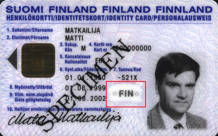
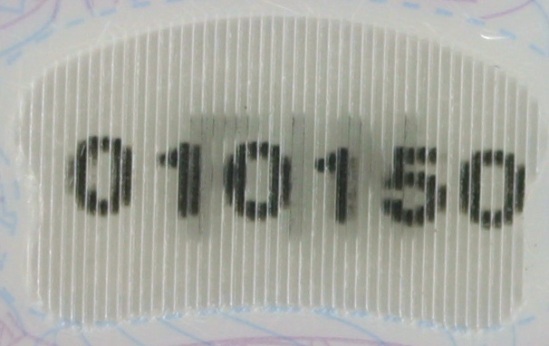
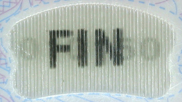
MULTIPLE LASER IMAGE MLI / CLI
MLI / CLI —Multiple Laser Image / Changeable Laser Image
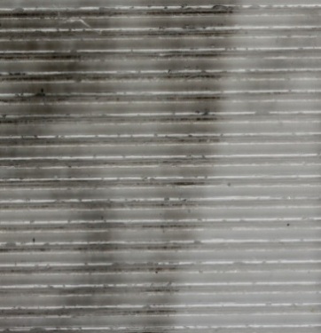
An image applied with the help of the lenticular technology, and changes depending on the angle of observation (flip-effect). The image consists of an array of cylindrical lenses (lenticular) and two scrambled images applied by laser engraving. Images may contain holder’s personal data. Images change with flip-effect depending on the angle of observation.
An array of lenses may be horizontally (fig. 1) and vertically (fig. 2) oriented.
a |

b |
c |
d |
e |
|
Fig. 1. Sweden. Temporary passport: |
||
a |
|
b |
c |
|
Fig. 2. Finland. Identity card: |
|
A printing technique which uses a flat plate with printing and spacing elements placed in the same plane. Inks are transferred from the plate to a rubber-blanket cylinder, then to the printing surface.
Traditional offset is an offset with dampening when printing and spacing elements are divided due to their physical and chemical properties. It means that spacing elements are applied by the area of the plate which attracts water, and printing elements are applied by the area of the plate which attracts an ink. Before every inking the printing plate is dampened with water. The water film stays only on spacing elements and they don’t attract the ink. Line images in passports are usually printed by mixed inks and rarely by triade inks (fig. 2).
Characteristics of the traditional offset print:
- the absence of a relief (the substrate is not deformed by pressure);
- an even distribution of the ink in strokes, thickness of the ink layer is permanent;
- paper fibers are visible through the strokes (fig. 1).
Dry offset is an offset without dampening. Silicone is used for a layer of printing elements which repulse the ink at the printing plate. Oil inks and UV-fluorescent inks are used for the dry offset printing.
High offset is a printing method which combines elements of letterpress and offset. An image is transferred from the letterpress printing plate to a rubber blanket and then to the printing surface. Printing pressure is lower than in letterpress and the printing plate does not contact the substrate so there is no concave relief.
Characteristics of the print:
- the absence of the relief and substrate deformation;
- the presence of the same boundary effects as in letterpress but it appears to a less extend (fig. 3).
a |
b |
|
Fig. 1. Switzerland. Official passport: |
|
a |
b |
c |
|
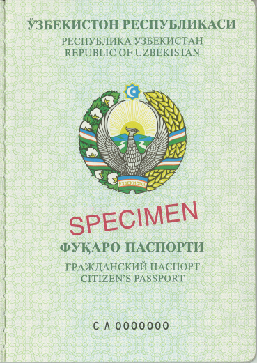
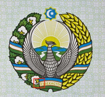
Fig. 2. Uzbekistan. Identity document of a minor citizen: |
||
a |
b |
|
Fig. 3. Sweden. Temporary passport: |
|
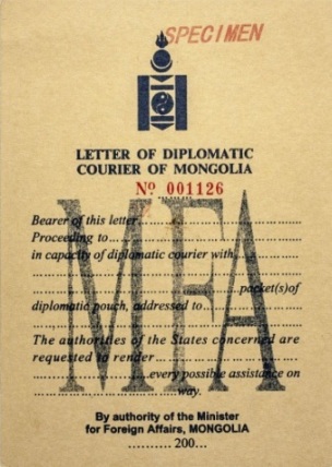
ONE-SHEET PAPER (SINGLE SHEET DOCUMENT)
A type of a document construction in the form of a paper sheet of any format, self-adhesive or not. A sheet document may be used as an independent document or may be sticked to the endpaper or inside pages of a document (fig. 1, 2).
a |
b |
a |
b |
|
Fig. 1. Mongolia. Diplomatic courier document (105×148 mm): |
Fig. 2. Sweden. Temporary passport (209×290 mm): |
||
OPTICALLY VARIABLE IDENTIFICATION ELEMENT FEEL-ID
A composite security feature based on colour changing and thermochromic effect. It was developed by Giesecke&Devrient company. FEEL-ID has a multilayer structure: 1) The top layer is made using STEP security feature with liquid crystal pigments; 2) The middle layer is made of thermochromic ink; 3) The bottom layer contains laser-engraved identification information (holder’s portrait, etc.).
FEEL-ID characteristic features:
- its colour changes at different angles of observation and illumination (colour changing effect, STEP element);
- identification information hidden beneath the thermochromic ink layer is revealed when exposed heat (thermochromic effect).

FEEL-ID element structure |

a |

b |

c |

d |

e |

f |
||||
|
Hungary. Passport (2006): |
|||||
OPTICALLY VARIABLE IDENTIFICATION ELEMENT FUSE-ID
A composite security feature with identification information about the document holder. FUSE-ID was developed by Giesecke&Devrient company. It is printed with optically variable ink (OVI) and laser engraved afterwards. The element is produced by a laser beam which moves sequentially over the image background area and leaves the image outline untouched. The laser energy discolors optically variable ink by changing its surface nanorelief and optical features. The image contrasts with the brightened background and looks darker. The image color is determined byinterference effect which appears on the layered structure of ink pigments.

a |

b |

c |

d |
|
Fig. 1. Latvia. Passport: |
|||
OVI — Optically Variable Ink
An ink which changes its color unevenly due to the angle of observation and illumination. A color changing effect is determined by a thin film interference of pigments placed in a transparent bounding ink medium. Pigments structure is based on so called Fabry–Pérot filter principle (fig. 1). Selective absorption of white light beams occurs as a result of interference and multiple reflection of beams by two reflective surfaces (AL, Cr) The waves which have not been absorbed determine the ink color that we may observe (fig. 2). Characteristics of the reflected light beam are determined by dielectric layer thickness (MgF2) and by the angle of observation.
Security features may be increased by using a microprinting (fig. 3).

Fig. 1. Cross-section of an optically variable ink pigment. Scheme of a color shift in reflected light: |
a |
b |
c |
d |
||
|
Fig. 2. Sweden. Diplomatic passport: |
||
a |
b |
c |
d |
||
|
Fig. 3. Czech Republic. Official passport: |
||
OPTICALLY VARIABLE INK WITH EMBOSSING
A complex optically variable security element. It contains an image printed by an optically variable ink OVI which plays a role of the background for the second image applied by blind embossing.
A dual optical effect appears when viewed at different angles of observation and illumination: a color change of the background image and visualization of the second image due a treatment of light and the shade which appears at the ridges of relief elements. An image which applied by blind embossing is not visible at a right angle (fig. 1).
a |
b |
c |
d |
e |
|
|
Fig. 1. Belgium. Passport: |
|
OPTICALLY VARIABLE MAGNETIC INK (SPARK, OVMI)
OVMI — Optically Variable Magnetic Ink
Optically variable ink OVI with the dynamic effect. Ink pigments are oriented with the help of magnetic field — image color changes after changing the angle of illumination and observation. The effect of a bright light stripe movement occurs. The ink is usually applied by the screen printing method and contains ferromagnetic pigments.
a |
b |
c |
d |
|
Fig. 1. China. Passport: |
|
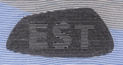
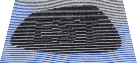
OPTICALLY VARIABLE PRINTED IMAGE DYNAPRINT
An image applied by the lenticular technology. Dynaprint consists of an array of cylindrical lenses (lenticular) and two scrambled images printed by offset (fig. 1). Color, brightness and contrast change relatively to the background depending on the angle of observation.
a |

b |
|
c |
d |
e |
|
Fig. 1. Estonia. Identity card: |
||
A method of a single-run multi-color printing invented by Ivan Orlov in 1890 in Russia. The Orlov printing is the formation of separate ink layers on color-separated plates and the transfer of the inks to the common plate and then to the receiving surface. In an Orlov printing machine a print is transferred from a plate directly to a paper sheet. In modern devices, an intermediate rubber cylinder (similar to the offset one) is used.
Charactirisics of the print:
- absence of a paper deformation appeared due to a printing plate pressure (for flat printing methods;
- even distribution of the ink in strokes, constant ink layer thickness;
- clear, sharp gradation of colors in strokes without breaks, shifts and overlapping (fig. 1).
a |
b |
c |
|
Fig. 1. Russia. Passport: |
||
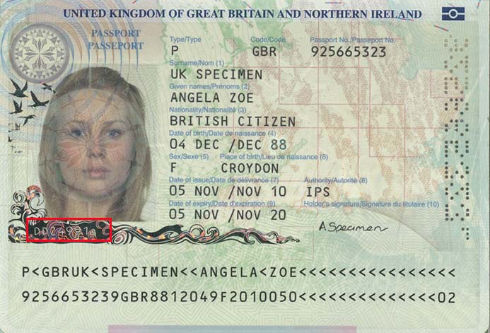
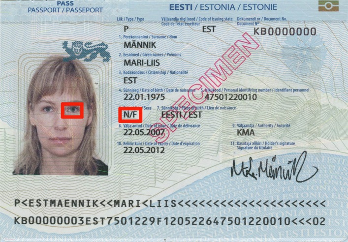
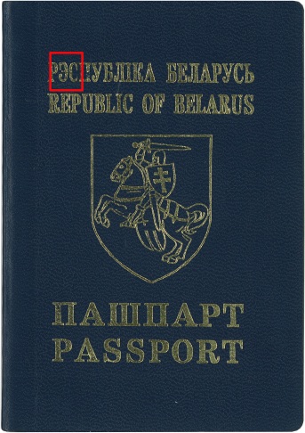
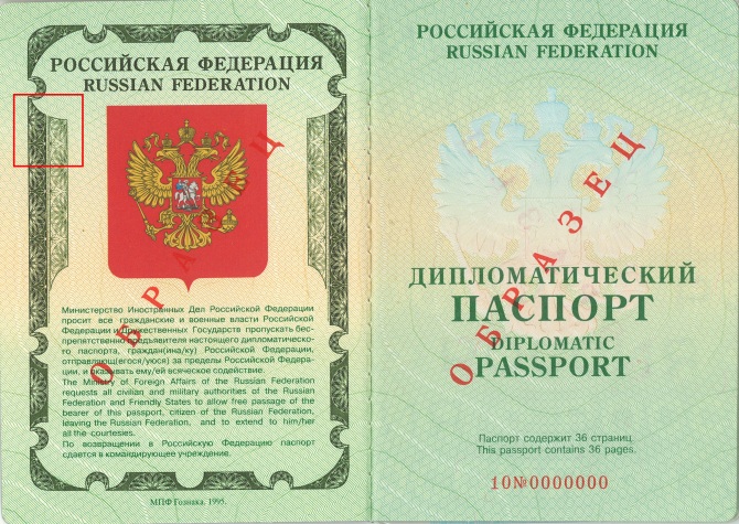
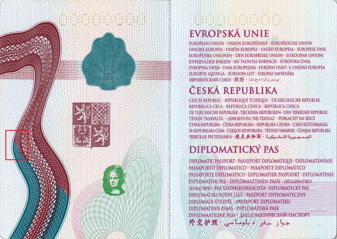
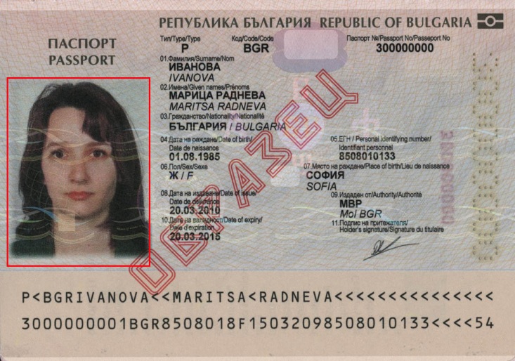
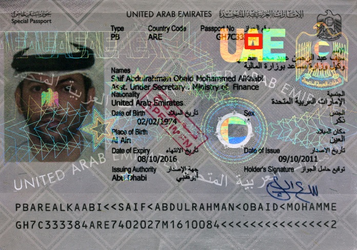
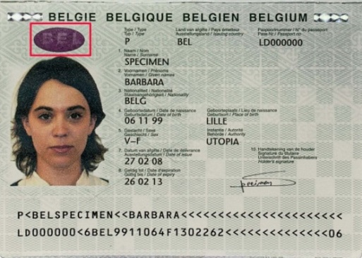
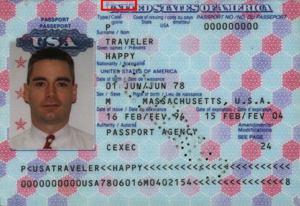
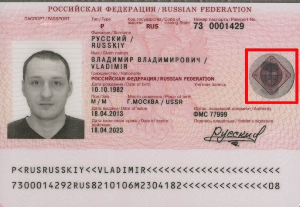
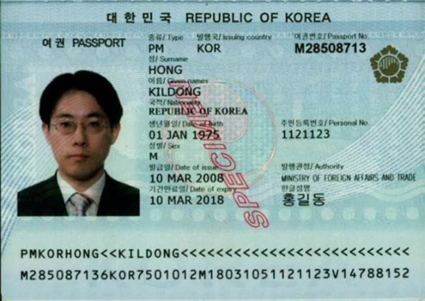
This is the main document that certifies the identity and gives a right to cross the border. A passport is issued to all individuals who are citizens or permanent residents of a corresponding country. A passport is a small book with a hard or a soft cover. It contains identifying information, security features, holder’s personal data, information about the issuing country and the issuing authority, blank pages for visas and other marks. Every country usually issued several types of passports: a national passport, a diplomatic passport, a service passport, an official passport, an alien’s passport, etc.
There are the following types of passports according to the way of personalization and data processing:
- passport without a machine-readable zone and an electronic medium (fig. 1);
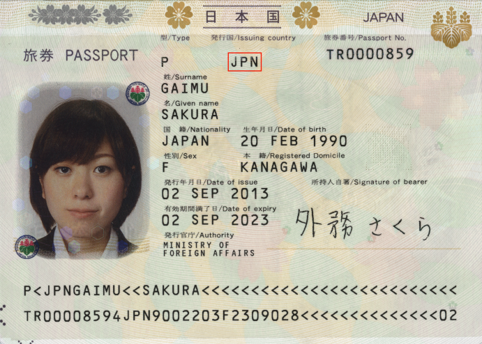
- passport with a machine-readable zone which contains a machine-readable data. This data consists of a combination of figures and letters which according to the international machine-readable travel documents standards must include the main data of the document (fig. 2);
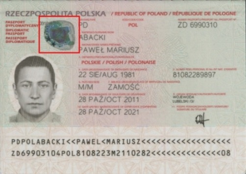
- • passport with an electronic medium (biometric passport) contains a microchip. The secured graphic and text data about the holder of the document is stored in the chip. A special logo in the form of a microchip is placed on the cover of a biometric passport (fig. 3).
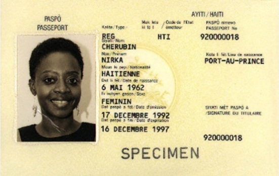 Fig. 1. Haiti. Passport. Fig. 1. Haiti. Passport.Data page without a machine-readable zone |
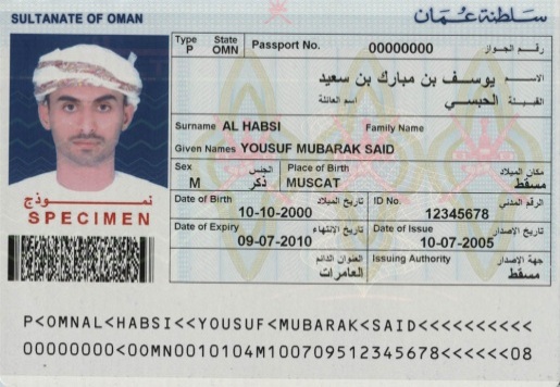 Fig. 2. Oman. Passport. Fig. 2. Oman. Passport.Data page with a machine-readable zone |
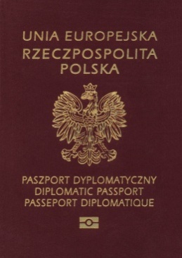
Fig. 3. Poland. Diplomatic passport. |
A type of a document construction which consists of a folded block of sheets stitched in the spine. It is binded with the help of endpapers or other techniques and then cut from three sides. Additional elements of a passport book are inserts.
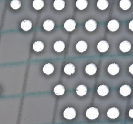
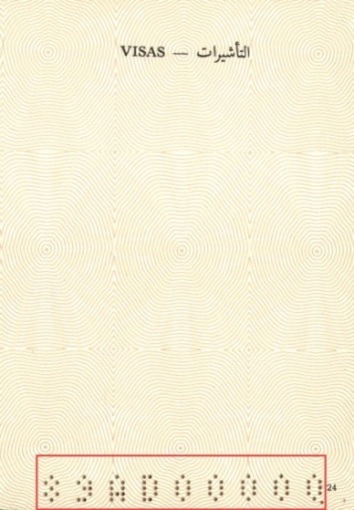
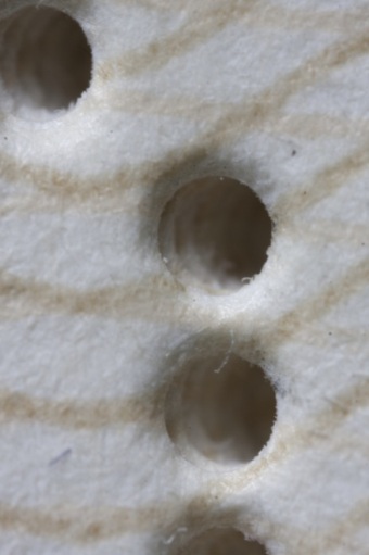
Holes in the substrate, which are located in a certain order. They can form a pattern (a holder’s portrait, a document number, etc.). There are laser (fig. 1, 2) and mechanical (fig. 3) perforation.
Laser perforation
Holes are created by a laser beam. They have a regular form, smooth edges and no raised edges on the reverse side. If several sheets are perforated simultaneously a conical decrease in size of the perforated holes is observed when viewed from front to back. Edges of a hole are slightly charred due to a laser beam exposure (fig. 2b).
Holes can vary according to a size and a shape. The density of perforated holes may vary. Laser perforation is used when applying:
- personal data, secondary holder’s image (fig. 1);
- document number (fig. 3);
If an image is perforated at an angle to the surface it is observed when tilting the page.
a |
b |
c |
|
Fig. 1. Sweden. Passport: |
||
a |
b |
|
Fig. 2. Australia. Passport: |
|
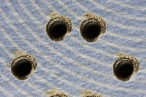
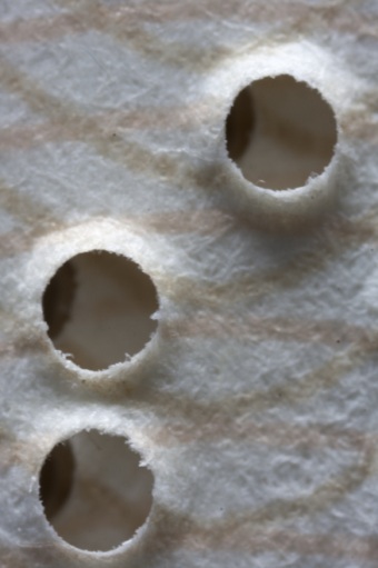
Mechanical (needle) perforation
Holes are made using the pressure of tubular metal needles. The edges of holes have ridges (“burrs”) which are tactile from the back of the substrate.
a |
b |
c |
|
Fig. 3. Djibouti. Diplomatic passport: |
||
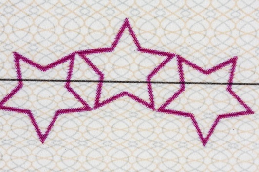
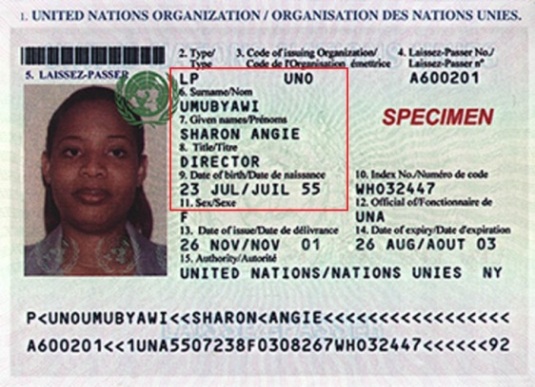
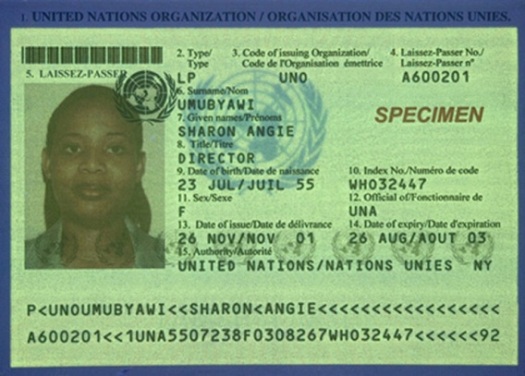
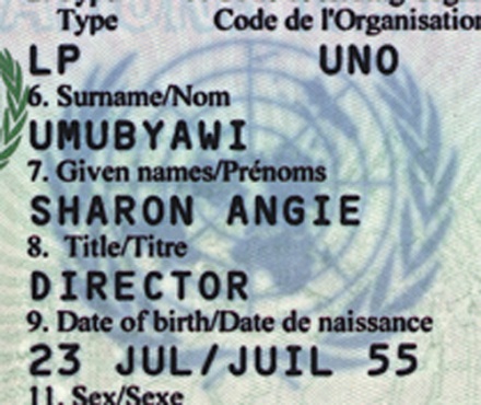
An ink containing photochromic pigments which change their color from transparent to red, yellow, blue, purple when exposed to UV light. When the UV light source is removed the image becomes pale and reverts to its original state (fig. 1). This process can be repeated an endless number of times.
a |
b |
c |
|
|
Fig. 1. United Nations. ID card: |
|
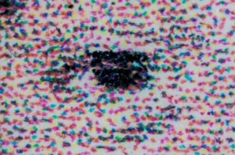
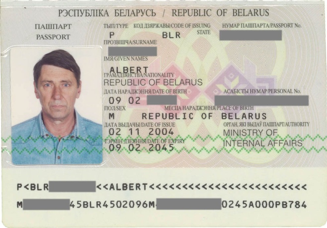
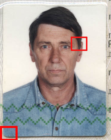
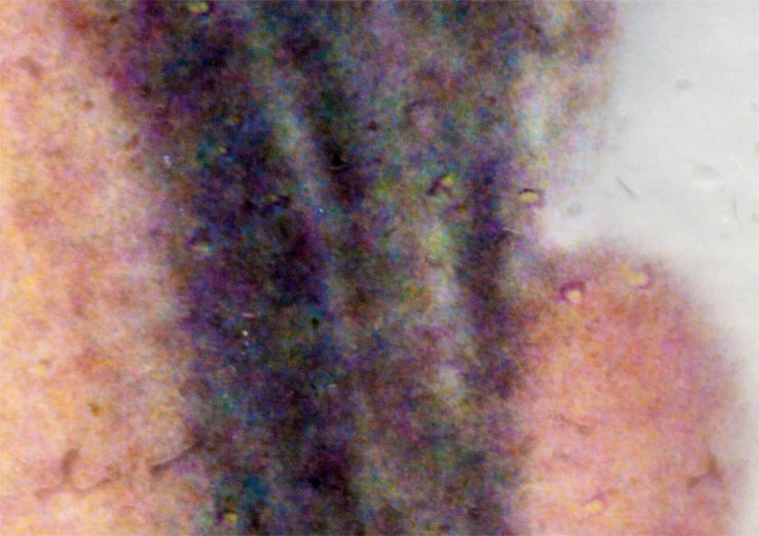
A visual image made by means of an optical device on a light-sensitive film and transferred to the photographic paper by chemical process. A photographic paper is covered by light-sensitive emulsion which contains silver bromides size less than 0,001 mm. Small silver particles appear on the areas of the emulsion which were exposed to light after a chemical treatment. They look like dim non-transparent spots which form dark areas. Areas which have not been exposed to light become light and transparent after development.
Characteristics:
- uneven structure formed by random clouds of small dye spots;
- smooth gradation and absence of a raster (fig. 1c, 1d).
a |
b |
c |
d |
|
Fig. 1. Belarus. Passport: |
|
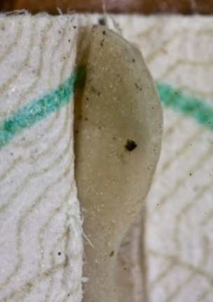
Thin round or many-sided pieces (scales) of 1-4 mm size which are made of polymer material. Planchettes are embedded into the substrate surface during the paper manufacturing process. They are placed randomly or located in a certain place of a sheet. Planchettes can be colorless, colorful, luminescent under UV light (fig. 1) or have the holographic effect. (fig. 2).
a |
b |
c |
|
|
Fig. 1. Australia. Passport – travel document. 2008: |
|
a |
b |
|
Fig. 2. The United States of America. Passport: |
|
A special security printing method using a technique in which two or more inks are applied on one printing plate. The printing is carried out with several inks from one color box divided by plates. Special rollers with fixed axial displacement in horizontal and vertical directions are used for printing (fig. 1, 2).
Characteristics of the print:
- equal ink distribution over the surface of a stroke;
- gradual color change when inks are merging into each other.
a |
b |
|
Fig. 1. Switzerland. Official passport: |
|
a |
b |
|
Fig. 2. Russia. Official passport: |
|
An optical device with the retroreflective effect. It consists of several layers (fig. 1):
- retroreflective layer with microlenses (microspheres);
- graphic image layer;
- reflecting layer.

Fig. 1. Retroreflective device scheme: |
When the surface is illuminated by parallel direct (coaxial) light beams, light semi-transparent images which are contrasting with the background are visualized (fig. 2). Microspheres focus light beams on the surface of the reflecting layer the way that reflected light returns towards the light source providing a clear visual perception of the image.
a |
b |
c |

d |
|
Fig. 2. Netherland. Travel document: |
|
A partial cutting of a substrate upper layer or a laminate coating which prevents a structural damage of a document made with the purpose of its forgery.
a |

b |
c |
|
Fig. 1. Korea. Passport: |
||
A printing technique, which enables to obtain an image by pushing the ink through the printing plate. The printing form is a frame made of a silk, synthetic fabric or metal threads. Spacing elements are covered by a layer which does not transfer an ink. Printing elements are open. A thin ink layer is evenly pushed through them by a rubber or polymer squeegee on the printing material during the printing process. This technique is used for printing images which don’t contain thin lines or small details.
Characteristics of the print:
- the absence of pressure and substrate deformation;
- a thick ink layer;
- zigzag or uneven edges of the image (fig. 1).
a |
b |
c |
|
Fig. 1. Slovakia. Travel document: |
||
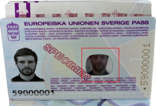
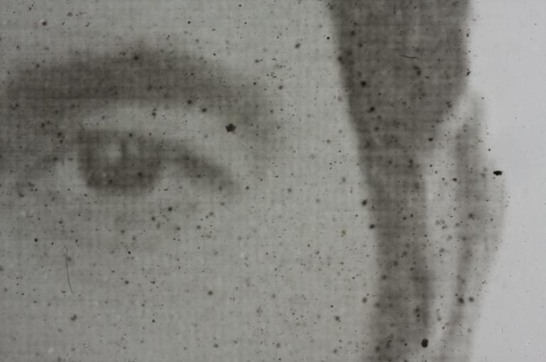
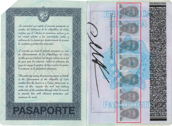
A secondary (reproduced once or twice) image of a holder’s portrait which is reduced in contrast and/or size. The image is usually printed using a different printing method than the one used for applying holder’s portrait. It can be located on the data page or other pages of a document.
The main techniques used for applying secondary image:
- laser perforation (fig. 1);
- laser engraving (fig. 2);
- laser printing (fig. 3);
- hologram (fig. 4);
- demetallisation (fig. 5);
- transparent UV-fluorescent inks (fig. 6).
a |
b |
|
Fig. 1. Sweden. Identity card: |
|
a |
b |
c |
|
Fig. 2. New Zealand. Diplomatic passport: |
||
a |
b |
|
|
Fig. 3. Cuba. Official passport: |
||
a |
b |
|
Fig. 4. Germany. Passport: |
|
a |
b |
|
Fig. 5. Russia. Passport: |
|
a |
b |
|
Fig. 6. Korea. Passport: |
|
An image (pattern, alphanumeric characters, etc.) located on the inner layer of a multilayer polycarbonate card with holder’s data. It is printed with special inks by a printing method. Secure core print is visible in transmitted light.

a |

b |

c |

d |
|
Рис. 1. Latvia. Passport: |
|||
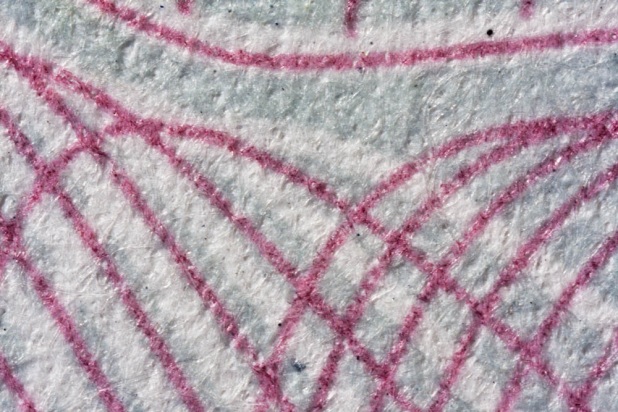
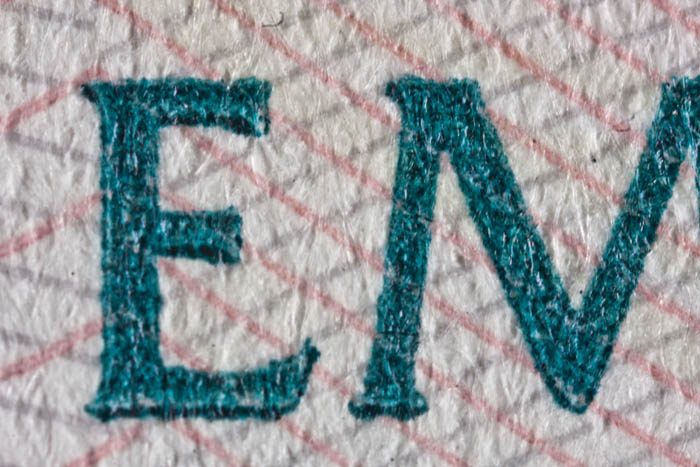
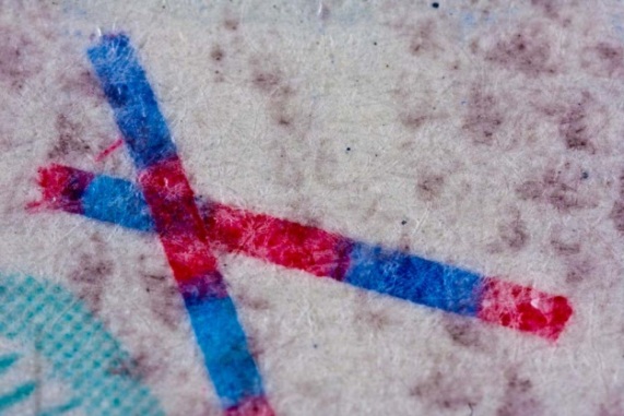
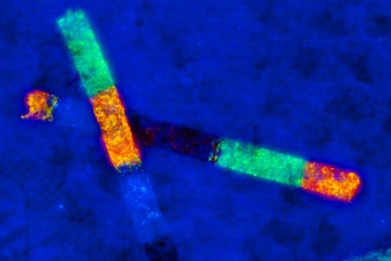
Fine visible or invisible fibres located randomly in the paper substrate. Fibres are embedded in the paper during its manufacturing process and distributed among other fibres of the paper pulp.
Security fibre classification:
By a perception degree with the naked eye:
- visible (fig. 1);
- invisible (fig. 2e, f).
By color:
- monochrome (fig. 1);
- two-color or multicolor with alternating areas of different colors (fig. 2c, d).
By presence of special security inks:
- UV-fluorescent;
- IR-fluorescent.
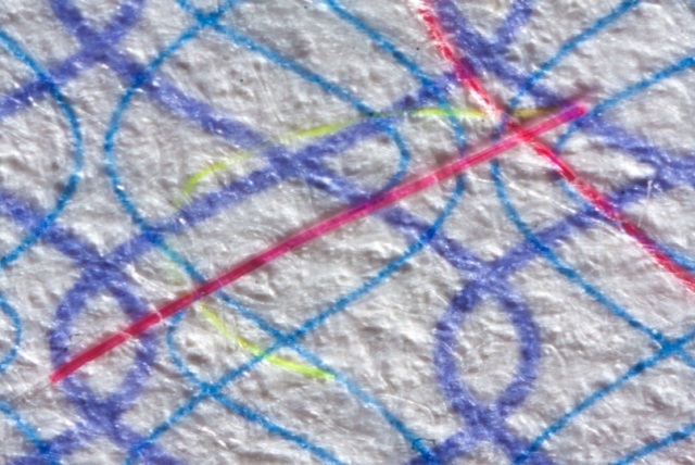
Fig. 1. Liechtenstein. Passport. |
|
a |
b |
c |
d |
e |
f |
|
Fig. 2. Great Britain. Passport: |
|
a |
b |
|
Fig. 3. Kosovo. Diplomatic passport: |
|
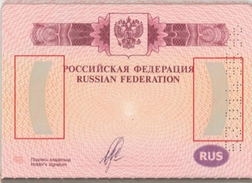
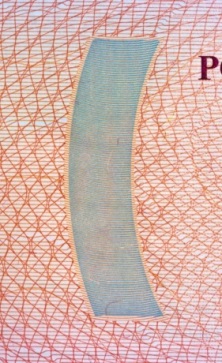
A narrow polymer-based stripe embedded in a paper web during the paper manufacturing process.
Security thread classification
By arrangement in the paper:
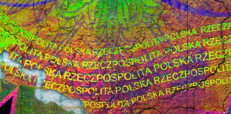
- latent security thread is completely embedded in the paper and visible in transmitted light only (fig. 1–3);
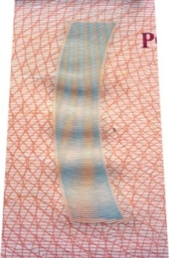
- window (diving) security thread appears partially on the paper surface (fig. 4, 6).
By material and security features:
- simple polymer (fig. 1);
- with a microtext (fig. 2);
- metallized with a color change effect (fig. 3);
- with the «floating» Motion image — when changing the angle of observation the effect of the image movement is observed on the security thread (fig. 4).
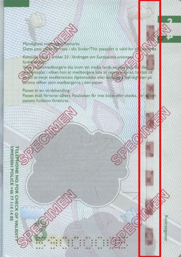
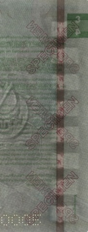
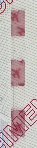
- UV fluorescent (fig. 5);
- IR fluorescent (fig. 6).
a |
b |
c |
d |
||
|
Fig. 1. Poland. Passport: |
||
a |

b |
c |
d |
||
|
Fig. 2. Kosovo. Diplomatic passport: |
||
a |
b |
c |
d |
e |
|||
|
Fig. 3. Russia. Passport: |
|||
a |
b |
c |
|
Fig. 4. Sweden. Temporary passport: |
||

a |
b |
c |
b |
|
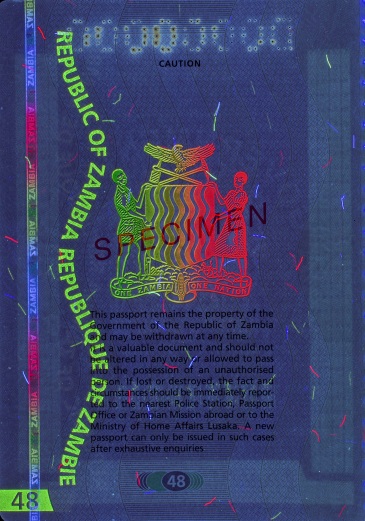
Fig. 5. Zambia. Diplomatic passport: |
Fig. 6. Italy. Diplomatic passport: |
||
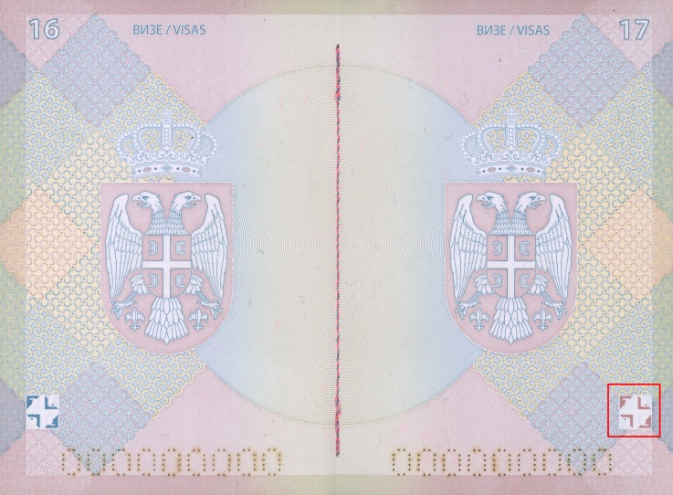
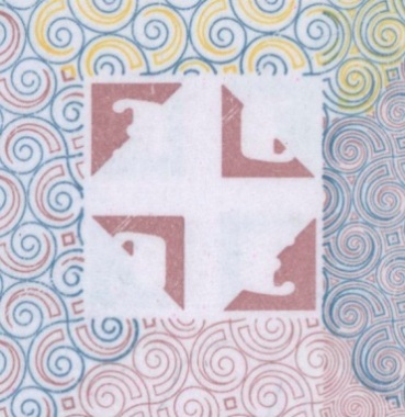
An image, a part of which is printed on one side of a sheet and the other part on the other side. When the sheet is viewed against the light, both parts match up and create a complete image without overlapping and gaps. A completed scene can only be viewed in transmitted light (fig.1). The image is printed in one pass.
a |
||
b |
c |
d |
|
Fig. 1. Serbia. Official passport: |
||
A transparent part of a multipage document which allows visualizing latent images, texts or codes located on an adjacent page of the document. During the verification process the filter is placed closely to the image area and scrambled data becomes clearly visible.
A self-verifying filter may have the form of a clear window in one of document pages or can be located on a transparent polycarbonate insert stitched into a passport book (fig. 1).

a |
b |

c |
|
Fig. 1. Belgium. Passport: |
||
A method of printing and visualization of images using a slit raster which allows getting an image changing effect depending on the angle of observation. A slit raster (optical analog of alenticular) is a transparent film on which a pattern is printed. The pattern consists of parallel transparent and non-transparent stripes. A scrambled interlaced image is printed under the slit raster (principle of coding is the same as in lenticular technology).
Depending on the angle of observation only one of stripes of the encoded image are visible through transparent stripes of the pattern. Non-transparent stripes blocked up the other stripe. Images are printed by offset or laser engraving (рис. 1–2).
a |
b |
|
Fig. 1. Slit raster technology scheme: |
Fig. 2. Scheme of image visualization at different angles of observation: |
The edge of a book block where all elements of a passport book are stitched.

a |

b |

c |
|
Fig. 1. Ireland. Passport. 2013: |
||
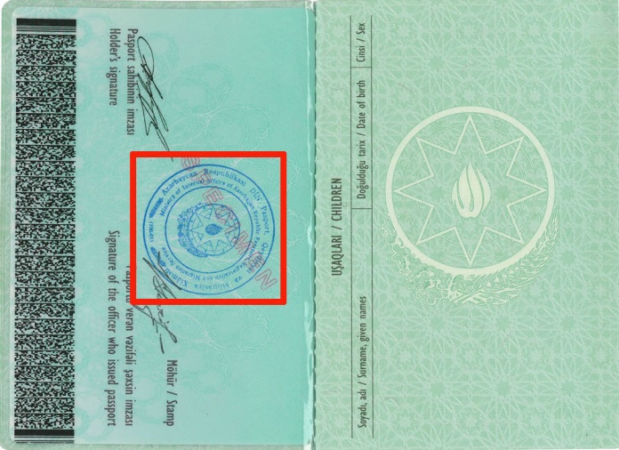
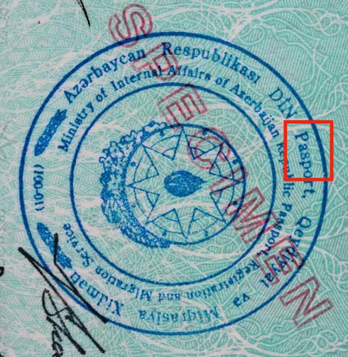
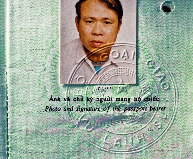
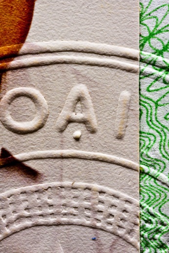
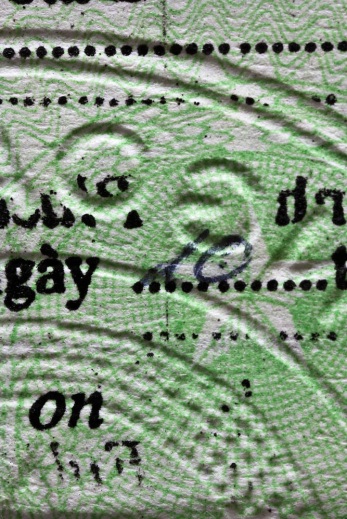
A seal, an impression, a mark or a relief formed on a paper substrate by means of a stamp pressure.
Types of stamps according to the application method:
- wet stamp is plain and applied with an ink (fig. 1);
- dry stamp is relief and applied without an ink (fig. 2).
Dry relief stamp is viewed under oblique light and perceived by touch. Substrate deformation is observed on both front and reverse sides (fig. 2c, d).
a |
b |
c |
|
Fig. 1. Azerbaijan. Passport: |
||
a |
b |
c |
d |
|
Fig. 2. Vietnam. Official passport: |
|
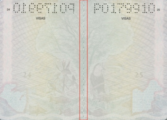
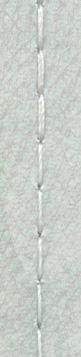
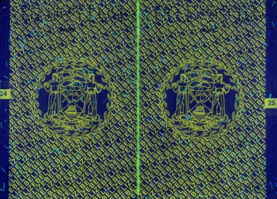
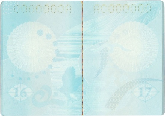
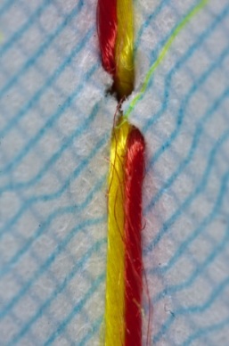
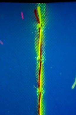
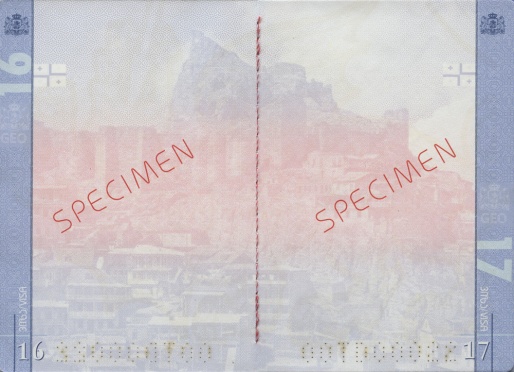
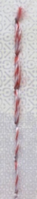
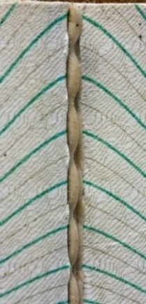
A material that is used for holding together the pages of a book block (fig. 1–4). A stitching thread consists of single threads, so called filament, twisted or stuck together. Stitching threads may vary on a number of threads, color, formation method and material. Synthetic threads with additional security features (luminescence in UV and IR-light, etc.) are usually used for stitching of passports and travel documents.
A stitching thread seam is a succession of stitches placed at regular intervals. There are following types of a seam in passport books: regular, complex double or triple stitched seams. Last stitches can be sewn several times.
a |
b |
c |
|
Fig. 1. Belize. Diplomatic passport: |
||
а |
б |
в |
|
Fig. 2. Kyrgyzstan. Passport: |
||
a |
b |
c |
d |
e |
|
|
Fig. 3. Georgia. Travel document: |
||
a |
b |
c |
|
Fig. 4. Denmark. Alien’s passport: |
||
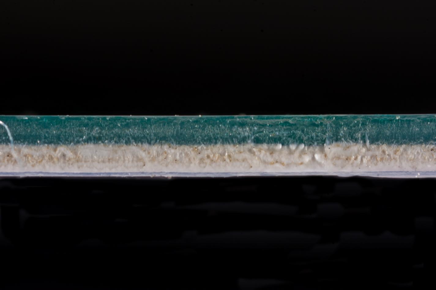
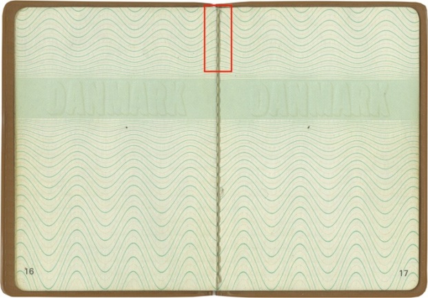
A special material used to produce documents, a background for applying images and embedding of security features.
Main types
Paper is a thin (4–400 mcm) sheet consisting mainly of specially treated small bounded and stitched plant fibers. A special paper is used for printing documents and securities. It contains such security features as watermarks, security fibres and threads, etc. Usually paper doesn’t luminesce in UV-light, contains special supplements and chemical components which prevents mechanical and chemical erasures and other types of forgery.
Photographic paper is a nontransparent material on a paper substrate with light-sensitive chemicals which is used for making positive photo image.
Polymer substrate is an acrylonitrile butadiene styrene, polyester, polycarbonate, polyvinyl chloride.
Fabric is a natural, synthetic, carton, denim or other coating materials which are used for producing document.
An ink which changes colour or becomes transparent at a certain transition temperature. Thermochromic effect is caused by changes in chemical composition or physical properties of thermosensitive pigments. Thermochromic ink may have more than two colour transitions depending on a certain transition temperature. It is applied by offset, letterpress or gravure printing on paper or polymer substrate.
There are two types of thermochromic inks:
- reversible inks change colour when they are heated to a temperature equal to or above the transition temperature. They return to the original colour when cooled to below their critical temperature;
- irreversible inks do not return to the original colour after cooling. It is caused by irreversible chemical or physical changes that take place when the ink is heated.

a |

b |

c |

d |

e |

f |

g |

h |

i |
|
Ireland. Diplomatic passport (2013): |
|||||
Thermographic printing (raised printing) is a post-print technology of producing a tactile raised print. The area printed by offset is dusted while wet with low-melting powder which sticks to the ink. The excess powder is removed from non-printed areas by shaking off or blowing off. Then the substrate is heated, and, as a result, the powder melts and forms a raised relief (raised ink) on the substrate. The powder that is used in thermography can be transparent, glossy or matte. Besides, transparent powder may be combined with metallized pigments or dyes of different colours.
|
a |
b |
|
Moldova. Temporary travel document: |
|
Thin-film interference is a phenomenon of two or more light waves superposition which causes their mutual amplification or reduction depending on how the phases of these waves are related to each other. A light beam 1 with a wavelength (λ) falls on the film at an angel (α) and is reflected at the point A. A light beam 2 travels in the film, is reflected from its lower boundary at the point B, is refracted at the point C and returns into the air (fig.1). The path difference appears between two adjacent reflected beams 1 and 2. A light beam 1 passes the distance equal to the interval ABC multiplied by the refractive index (n). But at the point C a part of the light beam is reflected down again, at the point В1 is reflected up, etc. Thus the connection of many waves occurs as a result of consequent reflections of incident light from the lower boundary of the transparent film. This calls multiple beam interference.
If the interval ABC is a whole number of wavelengths, their peaks and troughs will coincide and amplification of all the reflected waves will occur (interference maximum). When the film is illuminated by white light, consisting of waves of different frequency and length, light is refracted at the boundary between the media, and a part of the spectrum is eliminated. The interference maximum occurs for a specific wavelength (red, green or blue) at a certain film thickness and angle. In reflected light the film will have a color corresponding to a certain wavelength. This phenomenon is called “colors in thin films”.

Fig. 1. Multiple beam interference scheme: |

Fig. 2. Colours in thin films. |
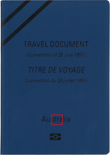
An official document issued by a state or an organization which is used by its holder for traveling to different countries and contains the obligatory visual inspection data.
Machine-readable travel document (MRTD) is also contains the obligatory brief data in the form which can be read and verified by machines.
Types of documents:
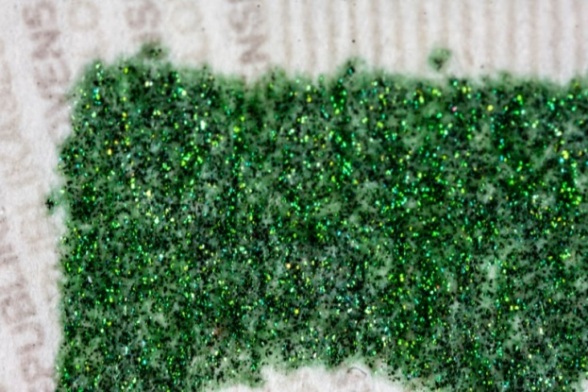
Small colored or colorless particles of a different size randomly embedded in the paper during the manufacturing process. The particles glow when exposed to UV light (fig. 1).
a |

b |
c |
|
Fig. 1. Greece. Alien’s travel document: |
||
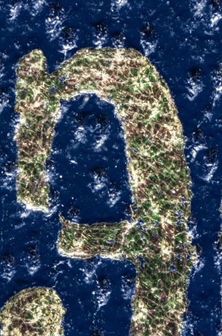
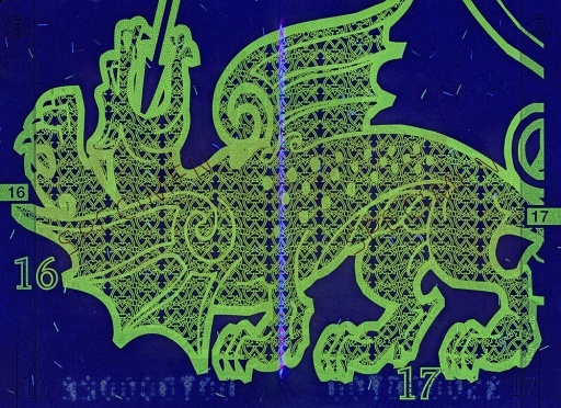
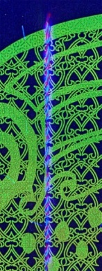
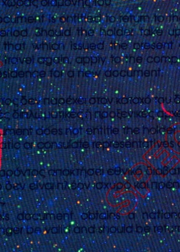
An ink containing color luminophores which transmit UV light into fluorescent light of different colors when exposed to UV light (250-380 nm). UV-fluorescent ink is not visible in white light by the naked eye. The ink is used for printing texts, images, secondary holder’s images or for dyeing security fibres, security threads, stitching threads (fig.1).
a |
b |
|
Fig. 1. Kosovo. Passport: |
|
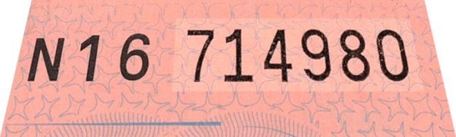
A transparent 20-40 mcm thick film which is invisible by the naked eye at a right angle. It protects the substrate from getting wet and prevents ink erasure. Varnish coating is visualized as a coating with slight gloss visible at an acute angle. It is applied over a printed image or creates an independent colorless image.
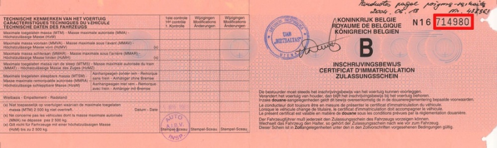
a
b |
|
Fig. 1. Belgium. Vehicle registration certificate: |
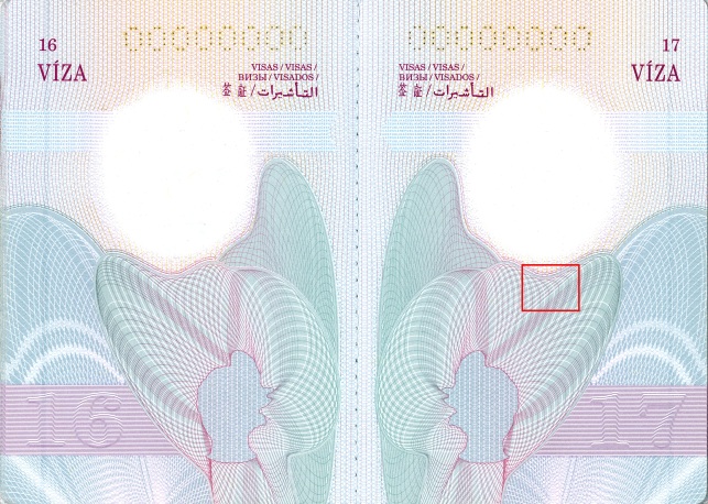
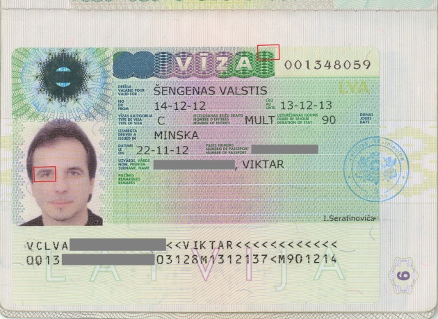
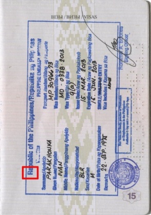
A permission to enter the territory of a country. Can be in the form of a sticker with a multilevel security system, an insert, a stamp or a small sticker. A visa is placed on special pages of a travel document. There are machine-readable (fig. 1а) and non-machine-readable (fig. 2, 3а) visas. Images may be printed using a printing method (fig. 1c), digitally printed (fig. 1b) or stamped (fig. 3b).
a |
b |
c |
|
Fig. 1. Belarus.Passport. page 6: |
||
 |
a |
b |
|
Fig. 2. Turkey. Non-machine-readable visa (sticker) |
Fig. 3. Philippines. Non-machine-readable visa (stamp): |
|
Machine-readable visas may be of two sizes:
- А size — full size — sized to completely fill a passport visa page;
- В size — small size — sized to maintain a clear area on the passport visa page adjacent to the visa to allow, for example, a seal to be placed on the visa and the passport page on which it is affixed or to allow reading a perforated number on passport pages.
A paper security feature which is visible in transmitted light as an image with slightly blurred, indistinct outlines and a smooth gradation of tones appeared due to local differences in paper density. A watermark is formed on a wet paper web in the process of paper production. It is formed by the density of fibres on certain areas of an image. Darker elements of a watermark are located on the more dense areas of paper. Lighter elements are located on the less dense areas.
Watermark classification
By location:
- General (UNPOSITIONED) watermark is an image repeated at regular intervals all over a document page (fig. 1);
- Local (POSITIONED) watermark is an image located in a certain place of a document page (fig. 2).
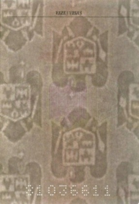
Fig. 1. Romania. Temporary passport. |
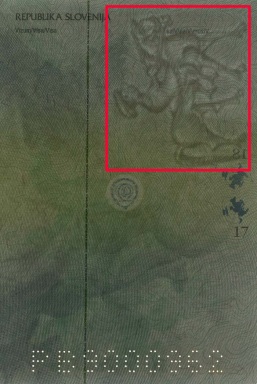
Fig. 2. Slovenia. Diplomatic passport. |
By general paper tone:
- Single tone watermark consists of dark or light elements of an image compared to a general paper tone (fig. 3);
- Duotone watermark consists of dark and light elements of an image compared to a general paper tone (fig. 4);
- Multi-tone (halftone) watermark consists of dark and light elements of an image compared to a general paper tone which are gradually transforming into each other (fig. 5).
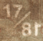
Fig. 3. Greece. Passport. 2011. |
Fig. 4.Israel. Passport. 2011. |

Fig. 5. Czech Republic. Passport. 2011. |
